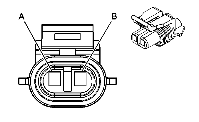
| Table 1: | Ambient Air Temperature Sensor (UH9/CJ2) |
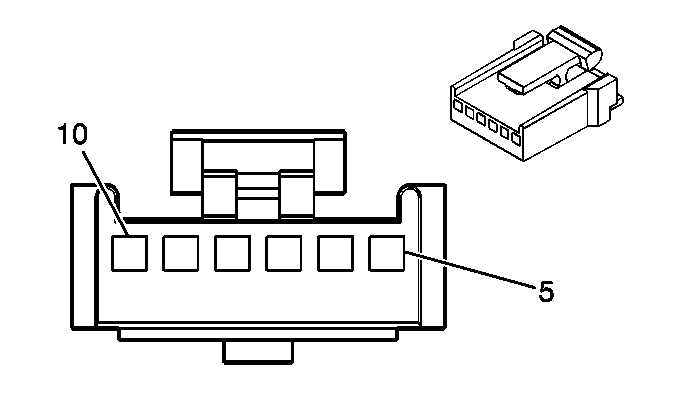
| Table 2: | Driver Information Center (DIC) Switch (UH6) |
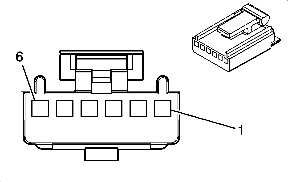
| Table 3: | Head Up Display (HUD) Switch (UH6) |
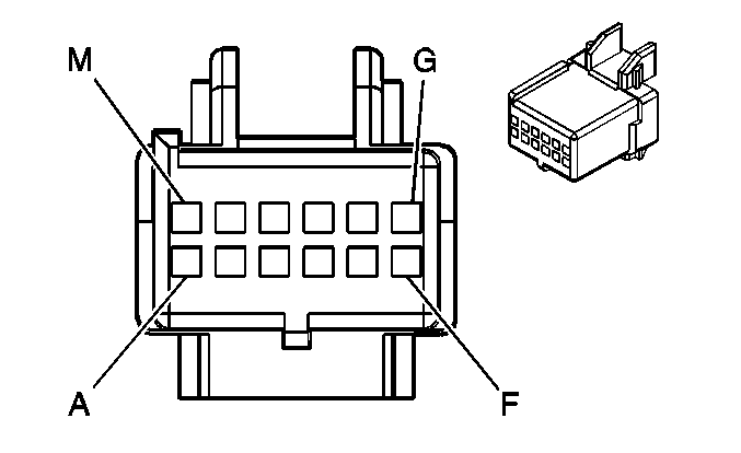
| Table 4: | Head Up Display (HUD) (UH6) |
| Table 5: | Instrument Panel Cluster (IPC) - Pontiac |
| Table 6: | Instrument Panel Cluster (IPC) - Buick |
| Table 7: | Ignition Key Alarm Switch |
| |||||||
|---|---|---|---|---|---|---|---|
Connector Part Information |
| ||||||
Pin | Wire Color | Circuit No. | Function | ||||
A | L-GN/BK | 735 | Ambient Air Temperature Sensor Signal | ||||
B | YE | 61 | Low Reference | ||||
| |||||||
|---|---|---|---|---|---|---|---|
Connector Part Information |
| ||||||
Pin | Wire Color | Circuit No. | Function | ||||
5 | GY | 8 | Instrument Panel Lamp Supply Voltage | ||||
6 | BK | 1450 | Ground | ||||
7 | BK | 1550 | Ground | ||||
8 | PK | 893 | DIC Select Menu Switch Signal | ||||
9 | D-GN/WH | 1358 | DIC Switch Signal | ||||
10 | -- | -- | Not Used | ||||
| |||||||
|---|---|---|---|---|---|---|---|
Connector Part Information |
| ||||||
Pin | Wire Color | Circuit No. | Function | ||||
1 | GY | 8 | Instrument Panel Lamp Supply Voltage | ||||
2 | BK | 1450 | Ground | ||||
3 | BK | 1550 | Ground | ||||
4 | YE | 621 | HUD Image Up Signal | ||||
5 | BN | 620 | HUD Image Down Signal | ||||
6 | WH | 717 | Illuminated Display Signal | ||||
| |||||||
|---|---|---|---|---|---|---|---|
Connector Part Information |
| ||||||
Pin | Wire Color | Circuit No. | Function | ||||
A | BK | 1550 | Ground | ||||
B | BK | 1450 | Ground | ||||
C | OG | 5240 | Battery Positive Voltage | ||||
D | L-BU | 14 | Left Turn Signal Lamps Supply Voltage | ||||
E | D-BU | 15 | Right Turn Signal Lamps Supply Voltage | ||||
F | WH | 717 | Illuminated Display Signal | ||||
G | BK | 9936 | Class 2 Serial Data | ||||
H | YE | 621 | HUD Image Up Signal | ||||
J | BN | 620 | HUD Image Down Signal | ||||
K-L | -- | -- | Not Used | ||||
M | BN | 241 | Ignition 3 Voltage | ||||
| |||||||
|---|---|---|---|---|---|---|---|
Connector Part Information |
| ||||||
Pin | Wire Color | Circuit No. | Function | ||||
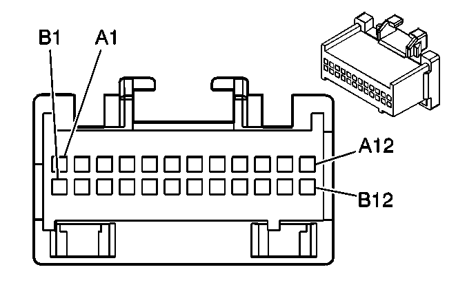
A1 | -- | -- | Not Used | ||||
A2 | BN/WH | 419 | MIL Control | ||||
A3 | D-BU | 15 | Right Turn Signal Lamps Supply Voltage | ||||
A4 | L-BU | 14 | Left Turn Signal Lamps Supply Voltage | ||||
A5 | TN/WH | 33 | Brake Fluid Level Switch Signal | ||||
A6 | D-GN/WH | 1358 | DIC Switch Signal (UH9) | ||||
A7 | PK | 893 | DIC Select Menu Switch Signal (UH9) | ||||
A8 | TN | 185 | Low Washer Fluid Indicator Signal | ||||
A9-A11 | -- | -- | Not Used | ||||
A12 | L-GN/BK | 735 | Ambient Air Temperature Sensor Signal (UH9) | ||||
B1 | OG | 640 | Battery Positive Voltage | ||||
B2 | YE | 61 | Low Reference (UH9) | ||||
B3 | BK | 1550 | Ground | ||||
B4 | PU | 1500 | Ignition 0 Voltage | ||||
B5-B6 | -- | -- | Not Used | ||||
B7 | BK | 1450 | Ground | ||||
B8 | GY | 8 | Instrument Panel Lamp Supply Voltage | ||||
B9 | GY | 1036 | IPC Class 2 Serial Data | ||||
B10-B12 | -- | -- | Not Used | ||||

| |||||||
|---|---|---|---|---|---|---|---|
Connector Part Information |
| ||||||
Pin | Wire Color | Circuit No. | Function | ||||
A1 | D-BU | 15 | Right Turn Signal Lamps Supply Voltage | ||||
A2 | TN/WH | 33 | Brake Fluid Level Switch Signal | ||||
A3 | TN | 185 | Low Washer Fluid Indicator Signal | ||||
A4 | PK | 893 | DIC Select Menue Switch Signal | ||||
A5 | D-GN/WH | 1358 | DIC Switch Signal | ||||
A6-A8 | -- | -- | Not Used | ||||
A9 | L-GN/BK | 735 | Ambient Air Temperature Sensor Signal | ||||
A10 | L-BU | 14 | Left Turn Signal Lamps Supply Voltage | ||||
A11 | BN/WH | 419 | MIL Control | ||||
A12 | -- | -- | Not Used | ||||
B1 | GY | 1036 | IPC Class 2 Serial Data | ||||
B2 | -- | -- | Not Used | ||||
B3 | GY | 8 | Instrument Panel Lamp Supply Voltage | ||||
B4 | -- | -- | Not Used | ||||
B5 | BK | 1450 | Ground | ||||
B6 | -- | -- | Not Used | ||||
B7 | PU | 1500 | Ignition 0 Voltage | ||||
B8 | -- | -- | Not Used | ||||
B9 | BK | 1550 | Ground | ||||
B10 | YE | 61 | Low Reference | ||||
B11 | -- | -- | Not Used | ||||
B12 | OG | 640 | Battery Positive Voltage | ||||
| |||||||
|---|---|---|---|---|---|---|---|
Connector Part Information |
| ||||||
Pin | Wire Color | Circuit No. | Function | ||||
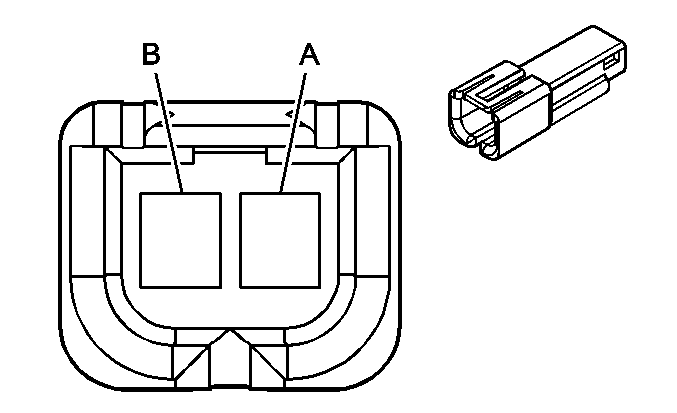
A | L-GN | 80 | Key In Ignition Switch Signal | ||||
B | BK | 1550 | Ground | ||||
