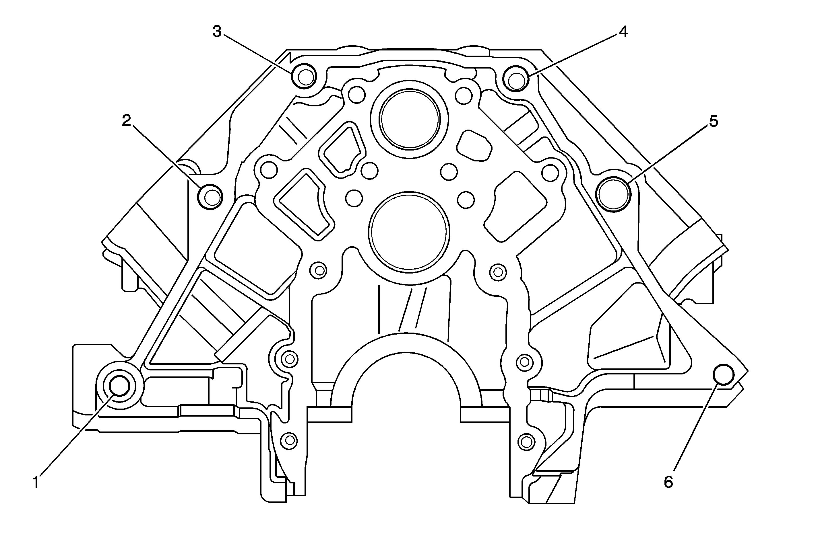
L36, L67, L26, L32, LA1, LX9, MN7, M15 Ticking or Knocking Type Noise Coming From Engine or Transmission Area (Replace Flexplate and Torque Converter)

| Subject: | L36, L67, L26, L32, LA1, LX9, MN7, M15 Ticking or Knocking Type Noise Coming From Engine or Transmission Area (Replace Flexplate and Torque Converter) |
| Models: | 2005 Buick Park Avenue |
| 2005-2006 Buick Allure (Canada Only), LaCrosse, LeSabre, Rendezvous, Terraza |
| 2005 Chevrolet Impala, Monte Carlo, Venture |
| 2005-2006 Chevrolet Malibu, Malibu Maxx, Uplander |
| 2005 Pontiac Aztek, Bonneville |
| 2005-2006 Pontiac Grand Prix, G6 GTP, Montana SV6 |
| 2006 Saturn Relay AWD |
| with 3800 3.8L Series III V6 Engine (VINs K, 1, 2, 4, -- RPOs L36, L67, L26, L32) or |
| 3500 3.5L V6 Engine (VINs L, 8 -- RPO LX9) or 3400 3.4L V6 Engine (VIN E -- RPO LA1) |
| and Hydra-matic 4T65-E Transmission (RPOs MN7, M15) |
This bulletin is being revised to update the warranty and parts information. Please discard Corporate Bulletin Number 06-06-01-014A (Section 06 -- Engine/Propulsion System).
Condition
Some customers may comment on a ticking or knocking type noise coming from the engine or transmission area.
Cause
Typically the noise is caused by either the transmission rear dust cover contacting the flexplate (refer to Corporate Bulletin Number 05-06-01-028) or a cracked flexplate (sometimes also referred to as a flywheel).
Correction
With the vehicle raised and supported on a suitable hoist, verify that the noise is coming from the flexplate area. If the noise is present, follow the procedure below. If the noise is not coming from the flexplate area, refer to Lower Engine Noise, Regardless of Engine Speed in SI.
Important: The following information only applies to vehicles with the noise coming from the flexplate area.
- Remove the front and rear transmission dust covers as described in Corporate Bulletin Number 05-06-01-028.
- With the covers removed, is the noise still present?
- Remove the starter motor. Refer to Starter Removal in SI.
- Remove the three bolts attaching the flexplate to the torque converter.
- After the three bolts have been removed, slightly move the torque converter away from the flexplate.
- Reinstall the starter motor and restart the engine.
- Is the noise still present?
- Remove the transmission assembly. Refer Transmission Assembly Removal in SI.
- Once the transmission is removed, inspect the flexplate on the rear of the engine for cracks.
- If crack(s) are found, remove the flexplate from the engine.
| • | If the noise is gone, then perform the steps found in Corporate Bulletin Number 05-06-01-028 to modify and reinstall the cover. |
| • | If the noise is still present, then proceed to Step 3 below. |
| • | If the noise is still present, it is NOT being caused by a cracked flexplate. Refer to SI for information on diagnosing the source of the noise. |
| • | If the noise is gone, proceed to Step 8 below. |
Important: Only proceed to the next step if crack(s) in the flexplate are found.

Parts Information
Part Number | Description | Engine RPO | Qty |
|---|---|---|---|
24508110 | Flexplate | L26, L36, L67 | 1 |
24506809 | Flexplate | L32 | 1 |
12579453 | Flexplate | LA1, LX9 | 1 |
Part Number | Year | Vehicle Model | Trans. RPO |
|---|---|---|---|
12491978 | 2005 | C | M15 |
12491978 | 2005 | H | M15 |
12491980 | 2005 | B | MN7 |
12491980 | 2006 | B | MN7 |
12491980 | 2005 | H | MN7 |
12491980 | 2005 | W | MN7 |
12491980 | 2006 | W | MN7 |
24212743 | 2004 | W | M15 |
24212743 | 2005 | W | M15 |
24212743 | 2006 | W | M15 |
24224255 | 2005 | B | M15 |
24224255 | 2006 | B | M15 |
24224255 | 2005 | U | M15 |
24224255 | 2006 | Z | M15 |
Warranty Information
For vehicles repaired under warranty, use:
Labor Operation | Description | Labor Time |
|---|---|---|
J1400 | Flywheel (Automatic Transmission/Transaxle) -- Replace | Use Published Labor Operation Time |
