For 1990-2009 cars only
Tools Required
J 45677 Frame Mount Installer/Receiver, or equivalent
Removal Procedure
- Using a wheel lift hoist, raise the vehicle. Refer to Lifting and Jacking the Vehicle in General Information.
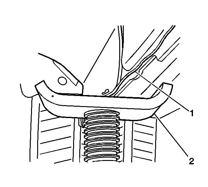
- Using utility stands (2), support some of the weight of the vehicle at the rear jacking points (1).
- Remove the rear shock absorbers. Refer to Shock Absorber Replacement .
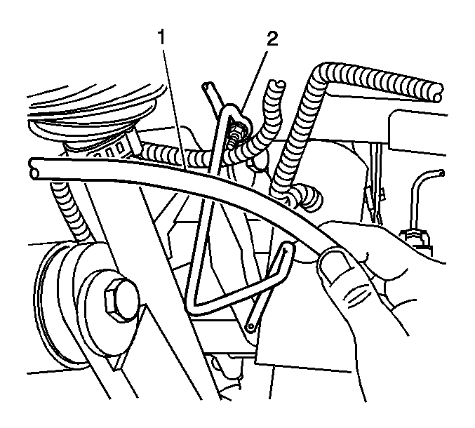
- Remove the right hand brake cable (1) from the left guide loop (2).
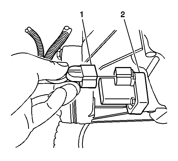
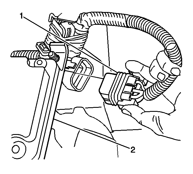
- For all wheel drive, disconnect the electrical connector (1) from the rear differential clutch pump check valve (2).
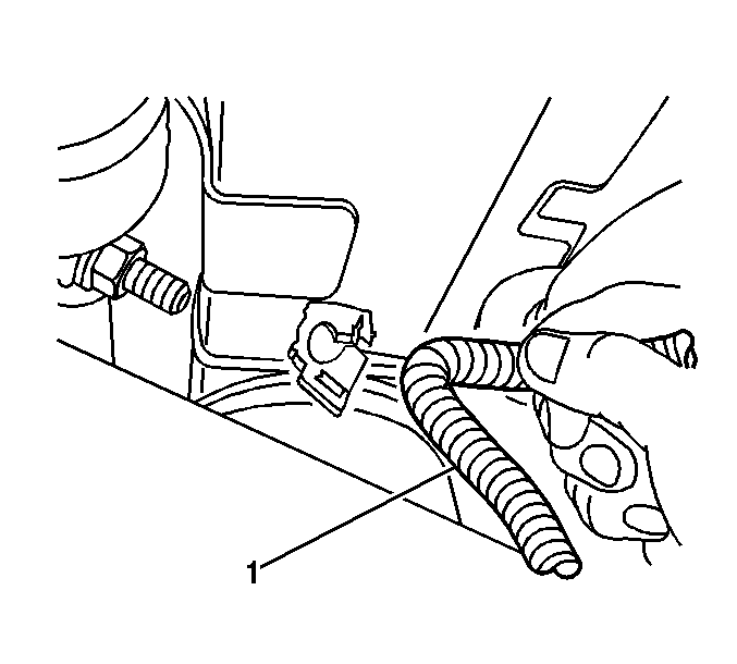
- Remove both ABS wiring harnesses (1) from the frame rails.
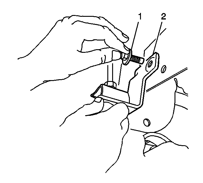
- Remove the brake hose mounting bolts (1) from the body brackets (2). Refer to Rear Brake Hose Replacement in Hydraulic Brakes.
- Disconnect the automatic level control (ALC) height sensor (2) harness connector (1).
- Lower the rear wheel lift hoist to unload the suspension partially, letting the utility stands take some of the vehicle weight .
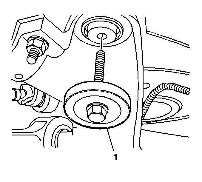
- Remove the rear crossmember mounting bolts (1). Refer to Crossmember Replacement .
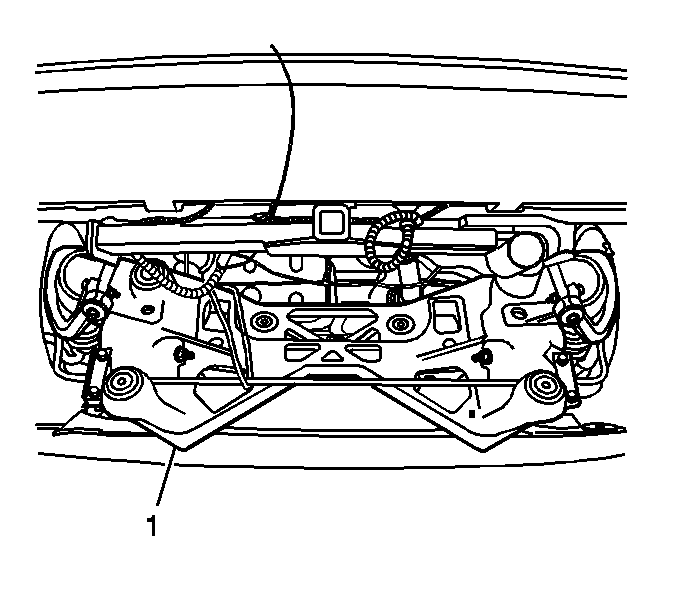
- With the help from an assistant , lower and rotate back the rear crossmember (1), approximately 114 mm (4 1/2 in) at the front mount, to install bushing removal/installation tool.
- Remove the rear crossmember frame mounts using J 45677 or equivalent .
Installation Procedure
- Install the new frame mounts using J 45677 or equivalent .
- With the help from an assistant, guide the rear crossmember (1) into place while the assistant raises the hoist.
- Install the rear suspension crossmember mounting bolts (1). Refer to Crossmember Replacement .
- Connect the ALC height sensor (2) harness connector (1).
- Install both ABS wiring harnesses (1) onto the frame rails.
- For all wheel drive, connect the electrical connector (1) into the rear differential clutch pump check valve (2).
- Install the right hand park brake cable (1) into the left guide loop (2).
- Install the brake hose mounting bolts (1) to the body brackets (2). Refer to Rear Brake Hose Replacement in Hydraulic Brakes.
- Install rear shock absorbers. Refer to Shock Absorber Replacement .
- Remove the utility stands (2).
- Lower the vehicle.
- Check the rear suspension toe alignment and adjust if necessary. Refer to Wheel Alignment Measurement in Wheel Alignment.
Important: Identify the orientation of the voids in the mounts and install the mounts with the voids fore and aft to the vehicle.

Notice: Refer to Fastener Notice in the Preface section.

Tighten
Tighten the bolts to 130 N·m (96 lb ft).


