Removal Procedure
Important: If the damage exceeds the recommended area for sectioning and the rail cannot be straightened, the complete rail must be replaced.
Sectioning procedures have been developed to simplify repair of the lower rails, providing the majority of the damage can be returned to factory specifications. This allows the damaged front section to be replaced without performing a full rail replacement. The rails come as a complete assembly. The front portion of the rail and bumper brackets are also serviced separately.
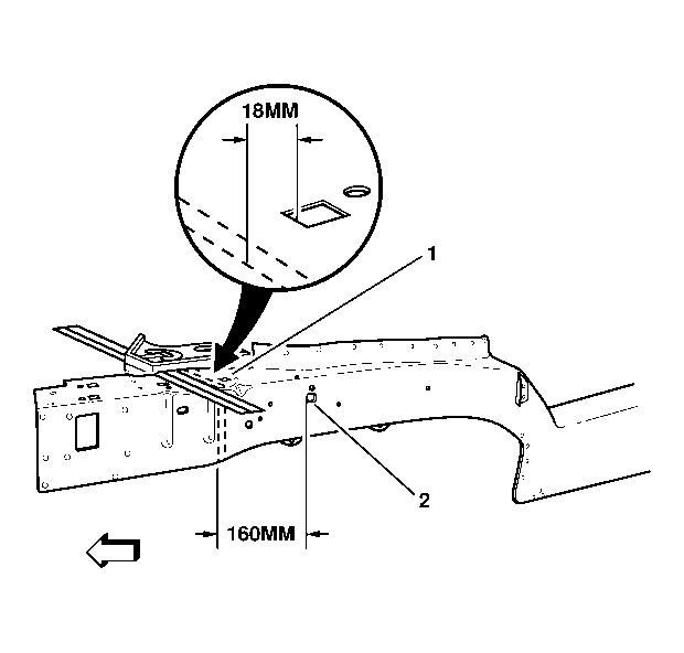
- On top of the rail, locate the last cut-out square (1). Measure forward 8 mm (5/16 in) and scribe a line.
- Add 10 mm (13/32 in) and scribe a second line. The second line 35 mm (1 3/8 in) is the cut location. The additional 10 mm (13/32 in) will be used to create a flange for welding the new service part to the vehicle.
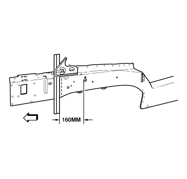
- On the outboard side of the rail, locate the fixturing hole (2). Measure forward 150 mm (5-29/32 in) and mark the location. Scribe a straight line on the rail.
- Measure forward 10 mm (13/32 in) and scribe a second line. The second line 160 mm (6 5/16 in) is the cut location.
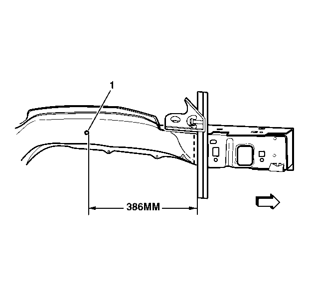
- On the inboard side of the rail, locate the brake line pass-thru hole (1). At the larger hole, pull the tape measure from the forward edge of the hole and mark a line at 376 mm (14-1/4 in). Scribe a line with a straight edge, making sure it is square to inboard and top rail markings.
- Measure forward 10 mm (13/32 in) and scribe a second line. The second line 386 mm (15 1/8 in) is the cut location.
- Cut through the three sides of the rail.
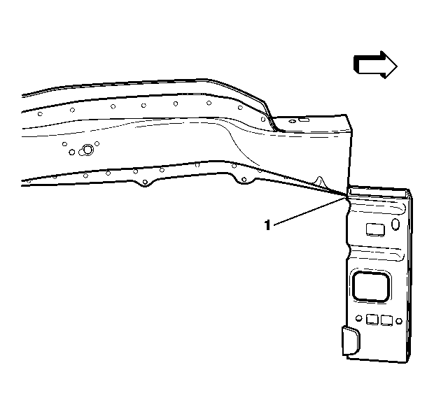
- On the bottom of the damaged rail, scribe a line from the outboard to the inboard cut locations and cut the remainder of the rail (1) from the vehicle.
- Remove the damaged section of the rail.
Important: Failure to follow the instructions included with the service rail may lead to improper rail sectioning, which may compromise the structural integrity of the vehicle.
Installation Procedure
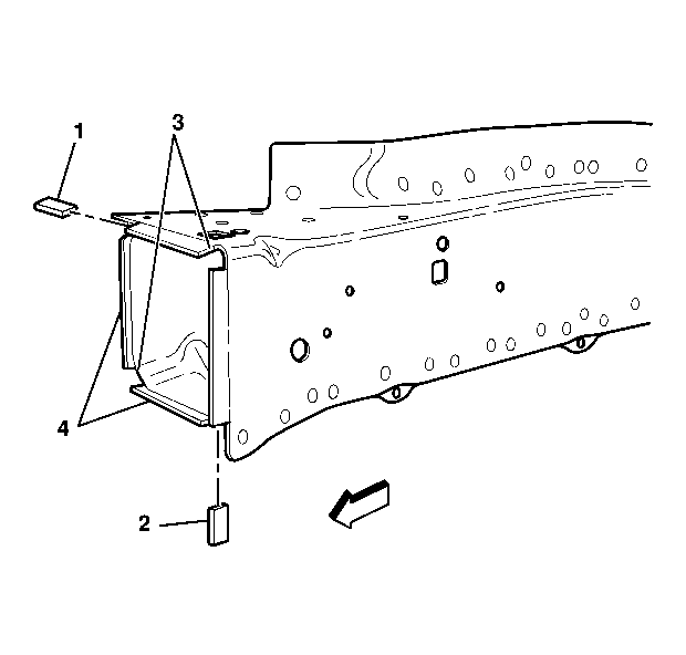
- On the original rail, cut and remove 10 mm (13/32 in) of the outboard (1) and downward (2) turned flanges of the rail. Cut 10 mm (13/32 in) gaps along the corners of the original rail.
- Step the top, bottom and side tabs inward (3) to allow the service part to fit over the original rail.
- Clean and prepare mating surfaces as necessary.
- Position the service part over the original rail. Align and check fit using three-dimensional measuring equipment.
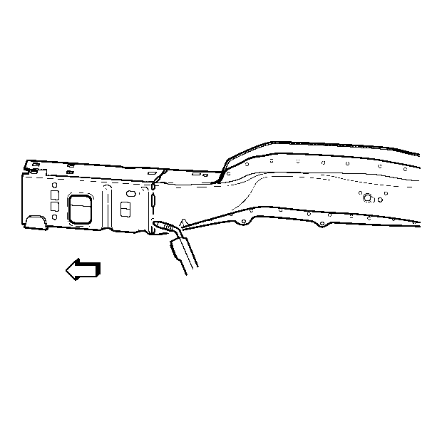
- Stitch weld along the entire sectioning joint. Make 25 mm (1 in) welds along the seam with 25 mm (1 in) gaps between them.
- Go back and complete the stitch weld. This will create a solid weld joint with minimal heat distortion.
- Clean and prepare all welded surfaces.
- Prime with two-part catalyzed primer.
- Apply sealers and anti-corrosion materials as necessary.
- Install all related panels and components.

Important: Prior to refinishing, refer to publication GM 4901M-D-01 GM Approved Refinish Materials for recommended products. Do not combine paint systems. Refer to paint manufacturer's recommendations.
