Tools Required
| • | J 28467-2A Radiator Tube Shelf Assembly |
| • | J 28467-3 Tube Assembly |
| • | J 28467-4A Front Support Assembly |
| • | J 28467-9 Quick Release Pin |
| • | J 28467-1A Cross Bracket |
Installation Procedure
Important: Supplemental support provided near the bottom of the transmission will be required to prevent the powertrain from rotating if the frame is lowered or removed.
- Remove the fuel injector sight shield.
- Remove the engine mount struts. Refer to
Engine Mount Strut Replacement - Right Side
and
Engine Mount Strut Replacement - Left Side
.
- One engine mount strut and nut can be reinstalled to the engine mount strut bracket on engine to be used as an attachment point for front engine attachment.
- Disconnect the electrical harness clip at the UHJB and at coolant housing.
- Disconnect the electrical connector at the engine control module (ECM).
- Remove the coolant recovery reservoir. Refer to
Coolant Recovery Reservoir Replacement
.
- Remove the power steering reservoir and bracket.
- Remove the attachment screw from the power steering pump reservoir to bracket.
Notice: Refer to Fastener Notice in the Preface section.
- Install the power steering reservoir bracket to powertrain.
Tighten
Tighten the power steering reservoir bracket bolts: M6 bolt to 9 N·m (7 lb ft) and M8 bolt to M8 Bolt to 25 N·m (18 lb ft).
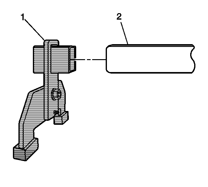
- Install a
J 28467-B
and retention pin to each end of the
J 28467-500
beam (2).
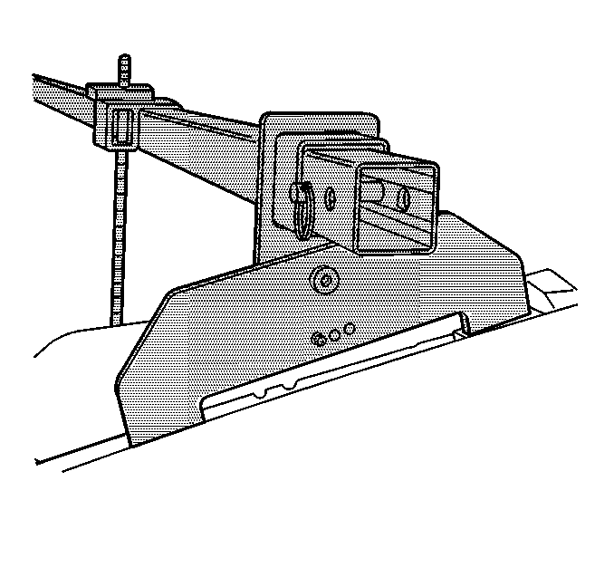
- Position the
J 28467-B
to the left and right side inner fender rails in order to install the
J 28467-500
.
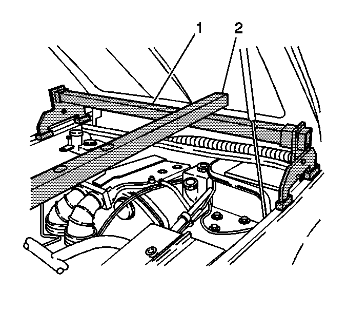
- Install the radiator shelf tube J 28467-2A (2) on top of the strut tower tube J 28467-3 (1) above the engine front (right bank)
lift bracket.
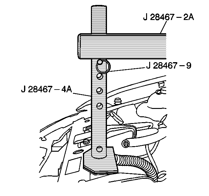
- Install the round tube of the front support assembly
J 28467-4A through the large hole in the radiator shelf tube J 28467-2A.
- Locate the J 28467-4A front support assembly to the upper tie bar.
- Install the J 28467-9 7/16 in x 2.0 in quick-release pin through the top hole in the J 28467-4A front support assembly.
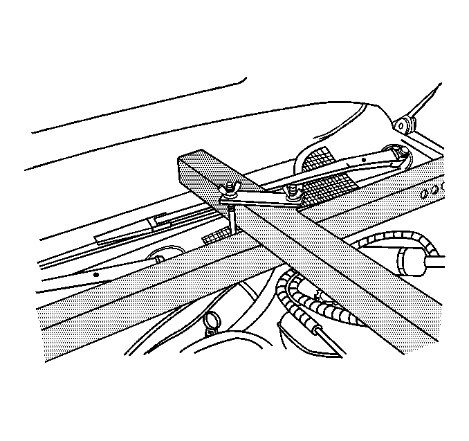
- Install the J 28467-1A cross bracket assembly.
- Assemble the following to create 2 lift hook assemblies as shown:
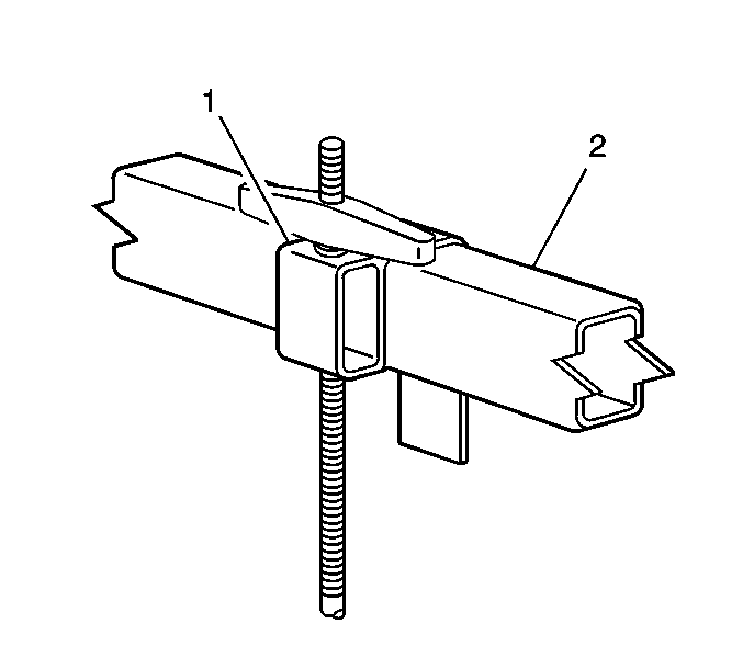
- Install the 2 lift hook assemblies (1) to the
J 45057-2
(2).
- Install the LH engine mount strut nuts and bolts to the strut brackets.
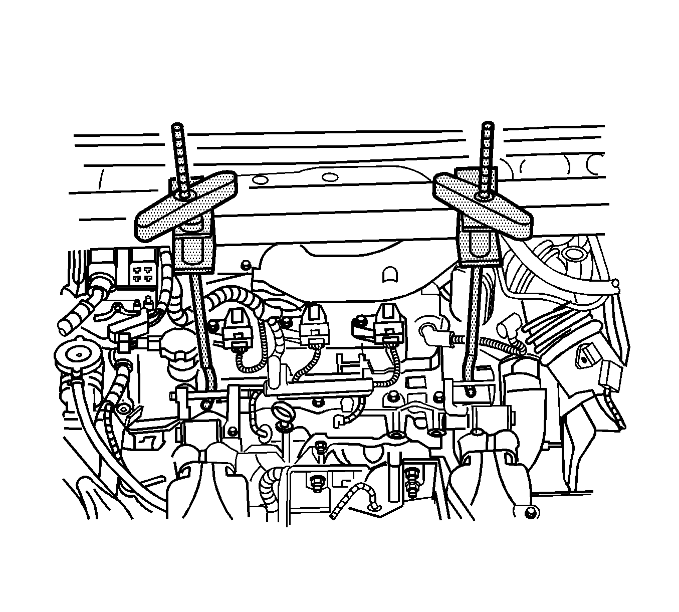
- Install the RH engine lift hook through the power steering reservoir bracket.
- Gently tighten the
J 28467-34
lift hook wing nuts to support powertrain.
Removal Procedure
- Remove the complete engine support fixture assembly.
- Remove the power steering reservoir bracket.
- Attach the power steering reservoir to bracket and install the screws.
Tighten
Tighten the power steering reservoir screws to bracket to 6 N·m (53 lb in).
- Install the power steering reservoir and bracket assembly.
Tighten
Tighten the power steering reservoir bracket bolts: M6 bolt to 9 N·m (7 lb ft) and M8 bolt to M8 Bolt to 25 N·m (18 lb ft).
- Install the engine mount struts. Refer to
Engine Mount Strut Replacement - Right Side
and
Engine Mount Strut Replacement - Left Side
.


