For 1990-2009 cars only
Power Steering Return Hose Replacement LA1
Removal Procedure
- Remove the drive belt. Refer to Drive Belt Replacement in Engine Mechanical - 3.4L.
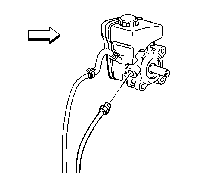
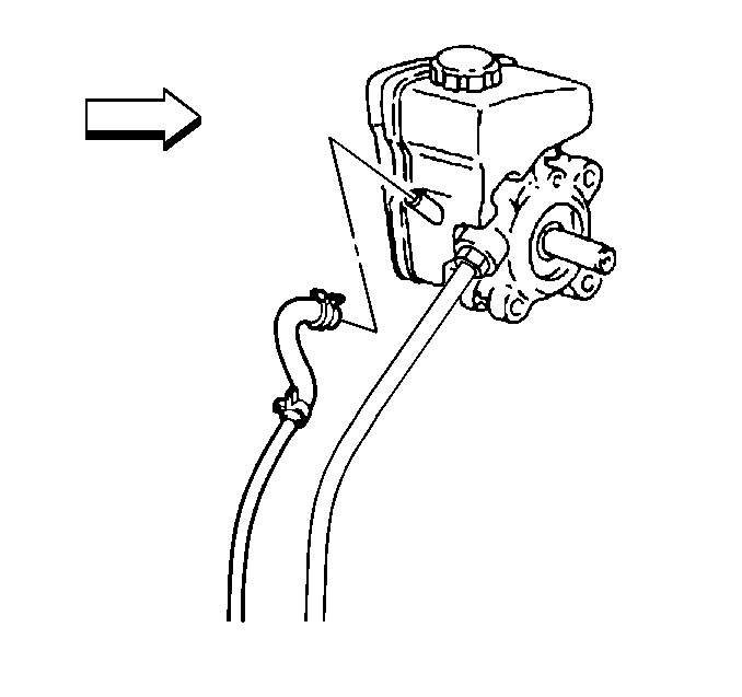
- Disconnect the pressure line from the power steering pump.
- Disconnect the return hose from the power steering pump.
- Raise and support the vehicle. Refer to Lifting and Jacking the Vehicle in General Information.
- Remove the right side engine splash shield. Refer to Engine Splash Shield Replacement in Body Front End.
- Disconnect both lines from the retaining clip.
- Disconnect the return line from the cooling pipe.
- Remove the return hose from the vehicle.
Installation Procedure
- Position the power steering return hose to the vehicle.
- Connect the return line to the cooler pipe.
- Connect both lines to the retaining clip.
- Install the right side engine splash shield. Refer to Engine Splash Shield Replacement in Body Front End.
- Lower the vehicle.
- Connect the return hose to the power steering pump.
- Connect the pressure line to the power steering pump.
- Install the drive belt. Refer to Drive Belt Replacement in Engine Mechanical - 3.4L.
- Bleed the power steering system. Refer to Power Steering System Bleeding .


Power Steering Return Hose Replacement LY7
Removal Procedure
- Siphon the power steering fluid from the reservoir.
- Raise and support the vehicle. Refer to Lifting and Jacking the Vehicle in General Information.
- Remove the right front tire and wheel. Refer to Tire and Wheel Removal and Installation in Tires and Wheels.
- Remove the inner fender liner enough to gain access to the front frame bolts. Refer to Front Fender Liner Replacement in Exterior Trim.
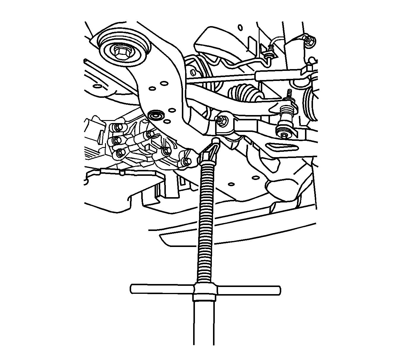
- Use a utility stand to support the right side of the frame.
- Remove the right side frame-to-body bolts.
- Use the utility stand to lower the right side of the frame and powertrain.
- Disconnect the power steering return hose from the power steering cooling pipe.
- Disconnect the power steering reservoir inlet hose from the power steering pump.
- Cap off the hoses, pipes and pump to prevent contamination.
- Use the utility stand to raise the frame and powertrain.
- Install the right side frame bolts.
- Lower the vehicle to allow a floor jack to engage with the frame.
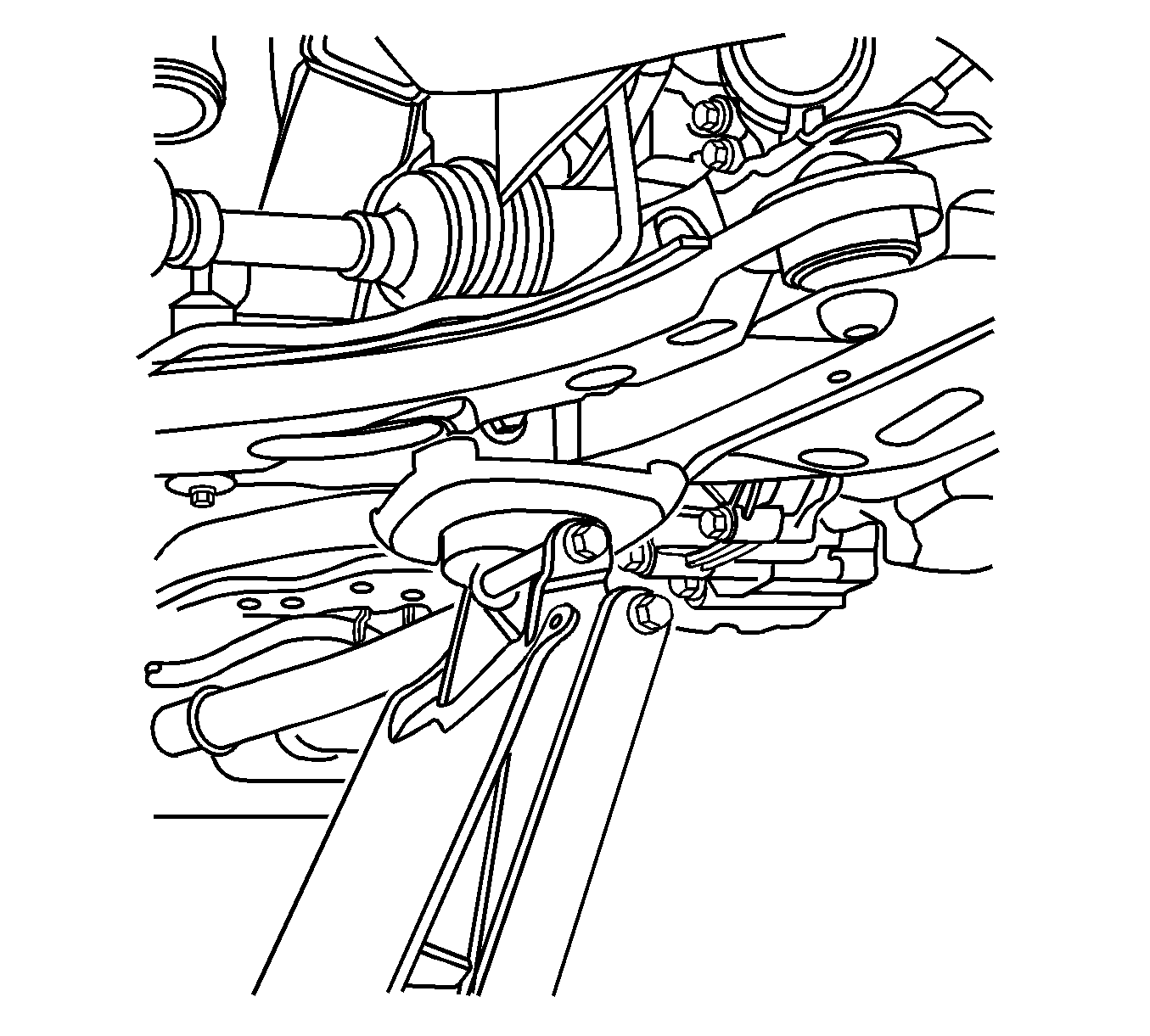
- Use a floor jack in order to support the frame and powertrain.
- Remove the right side frame-to-body bolts
- Use the floor jack to lower the right side of the frame and powertrain to provide clearance to the reservoir.
- Disconnect the ECM wire harness from the ECM wire harness clip on the reservoir.
- Remove the power steering pressure pipe/hose from the power steering reservoir bracket. Refer to Power Steering Pressure Pipe/Hose Replacement .
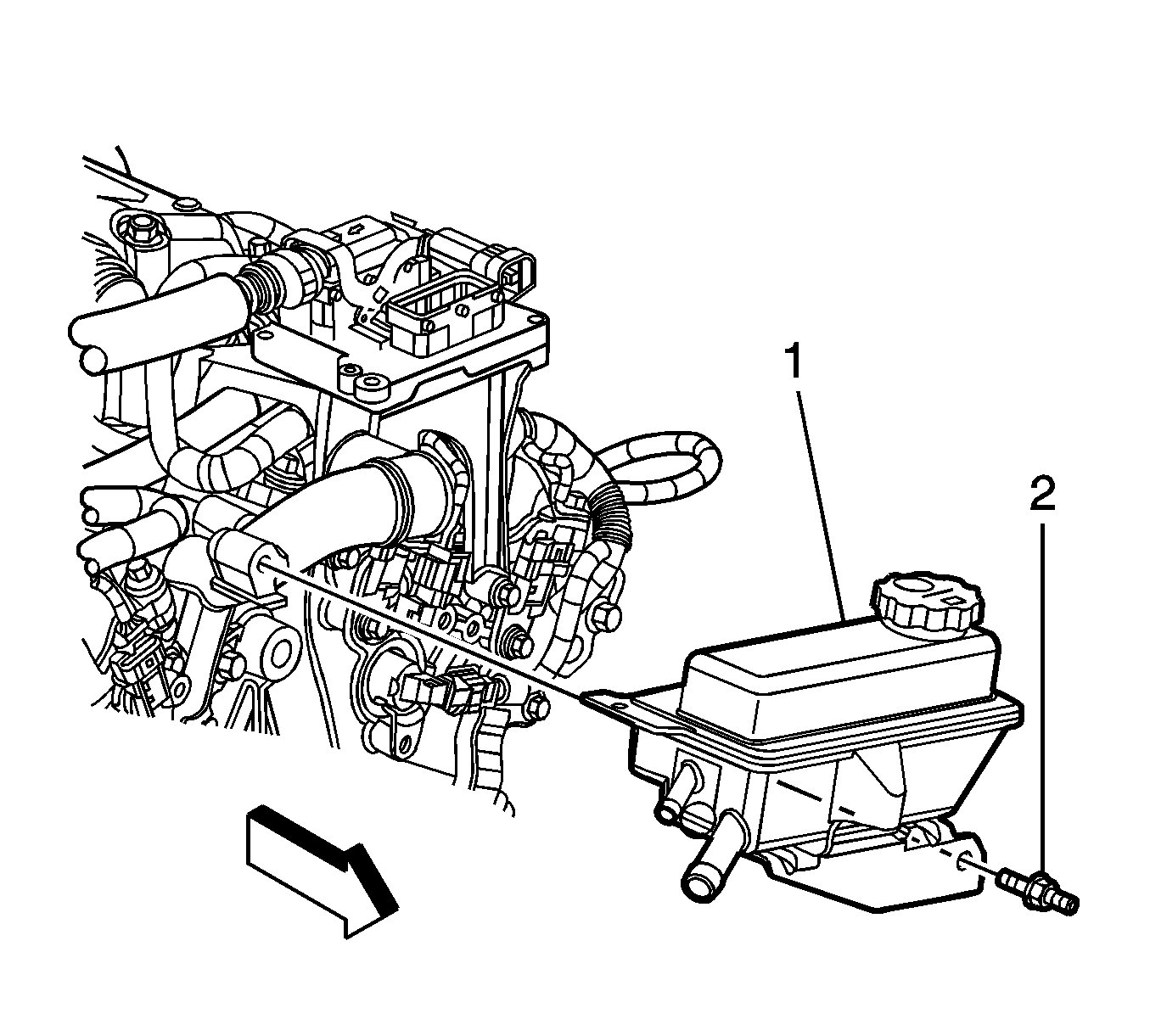
- Remove the power steering reservoir mounting stud bolt.
- Remove the power steering reservoir, reservoir bracket, and both hoses from the vehicle.
- Disconnect the power steering reservoir outlet hose from the power steering reservoir.
Installation Procedure
- Connect the power steering reservoir outlet hose to the power steering reservoir.
- Install the power steering reservoir, reservoir bracket, and both hoses to the vehicle.
- Install the power steering reservoir mounting stud bolt.
- Install the power steering pressure pipe/hose to the power steering reservoir bracket. Refer to Power Steering Pressure Pipe/Hose Replacement .
- Connect the ECM wire harness to the ECM wire harness clip on the reservoir.
- Use the floor jack to raise the right side of the frame and powertrain .
- Install the right side frame-to-body bolts
- Remove the floor jack from the frame and powertrain.
- Raise and support the vehicle. Refer to Lifting and Jacking the Vehicle in General Information.
- Use the utility stand to support the right side of the frame .
- Remove the right side frame-to-body bolts
- Use the utility stand to lower the right side of the frame and powertrain.
- Uncap the hoses, pipes and pump .
- Connect the power steering reservoir inlet hose to the power steering pump.
- Connect the power steering reservoir return hose to the power steering cooling pipe.
- Use the utility stand to raise the right side of the frame and powertrain.
- Install the right rear frame-to-body bolt.
- Install the right front frame-to-body bolt.
- Install the inner fender liner . Refer to Front Fender Liner Replacement in Exterior Trim.
- Install the right front tire and wheel. Refer to Tire and Wheel Removal and Installation in Tires and Wheels.
- Lower the vehicle.
- Fill the power steering reservoir with power steering fluid. Refer to Checking and Adding Power Steering Fluid .
- Bleed the power steering system. Refer to Power Steering System Bleeding .
- Inspect the system for leaks. Refer to Power Steering Fluid Leaks .
Notice: Refer to Fastener Notice in the Preface section.

Tighten
Tighten the power steering reservoir mounting stud bolt to 25 N·m (19 lb ft).


Notice: Refer to Fastener Notice in the Preface section.
Tighten
Tighten the right rear frame-to-body bolt to 240 N·m (177 lb ft).
Tighten
Tighten the right front frame-to-body bolt to 155 N·m (114 lb ft).
