GM Service Manual Online
For 1990-2009 cars only
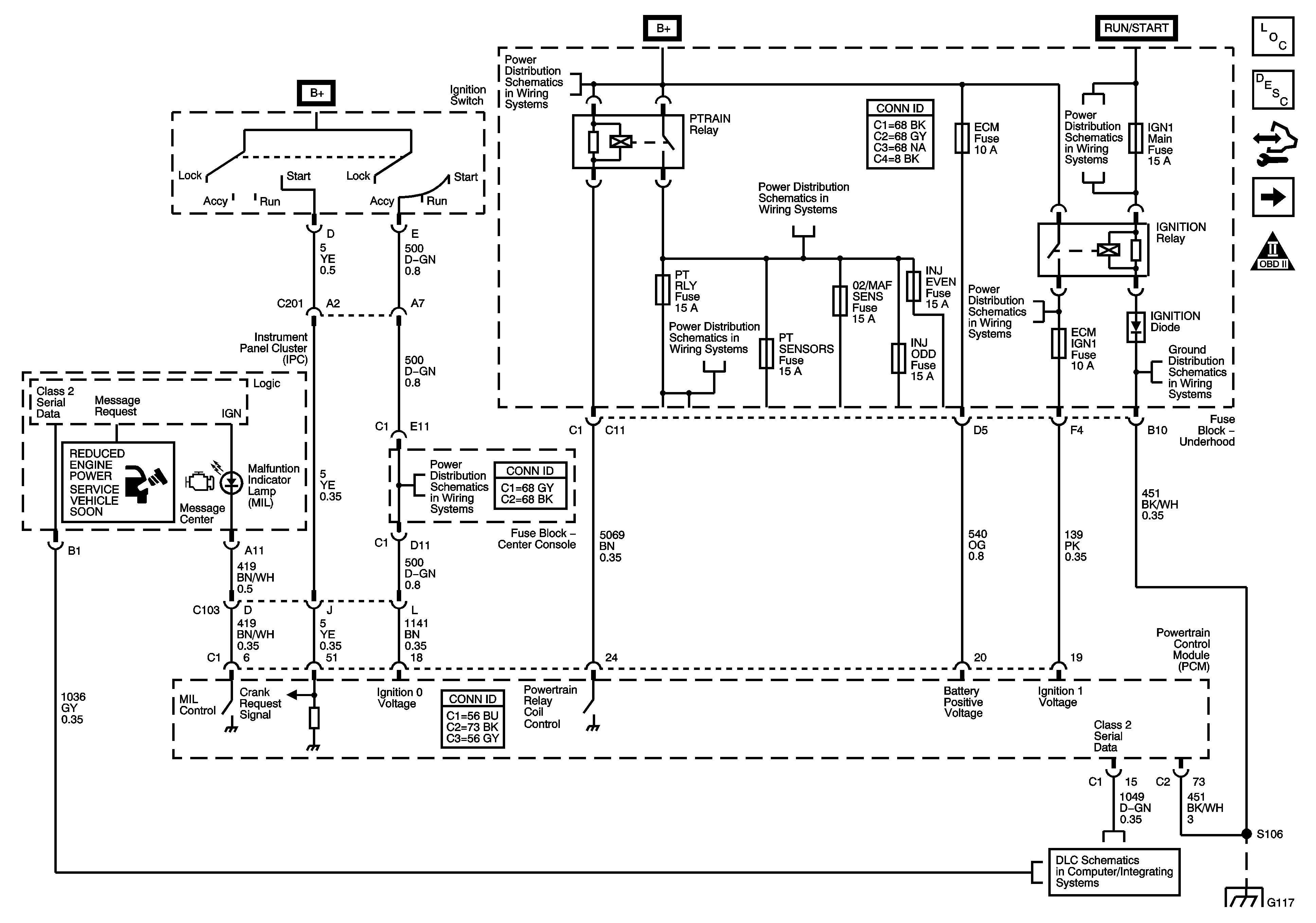
Figure 1:

Module Power, Ground, Serial Data, and MIL

Object Number: 1619474  Size: FS
Master Electrical Component List
Powertrain Control Module Description
Control Module References
Engine Data Sensors-5-Volt and Low Reference
Engine Controls Schematic Icons
Ignition Switch-ACCY/RUN/START and RUN and START Bus Bars, HVAC BLWR, IPC/BCM/PK3, PK3, and PRK LCK IGN Fuses
B+ Bus 2 of 2
PTRAIN Relay-2 of 2, BTSI, PT RLY, and PT SENSORS Fuses-LX9
IGNITION Relay, ABS, AWD, ECM IGN1, and TRANS Fuses
CRUISE, IGN1 MAIN, and TRN SIG Fuses
G117 and G132
DLC Schematics
G117 and G132
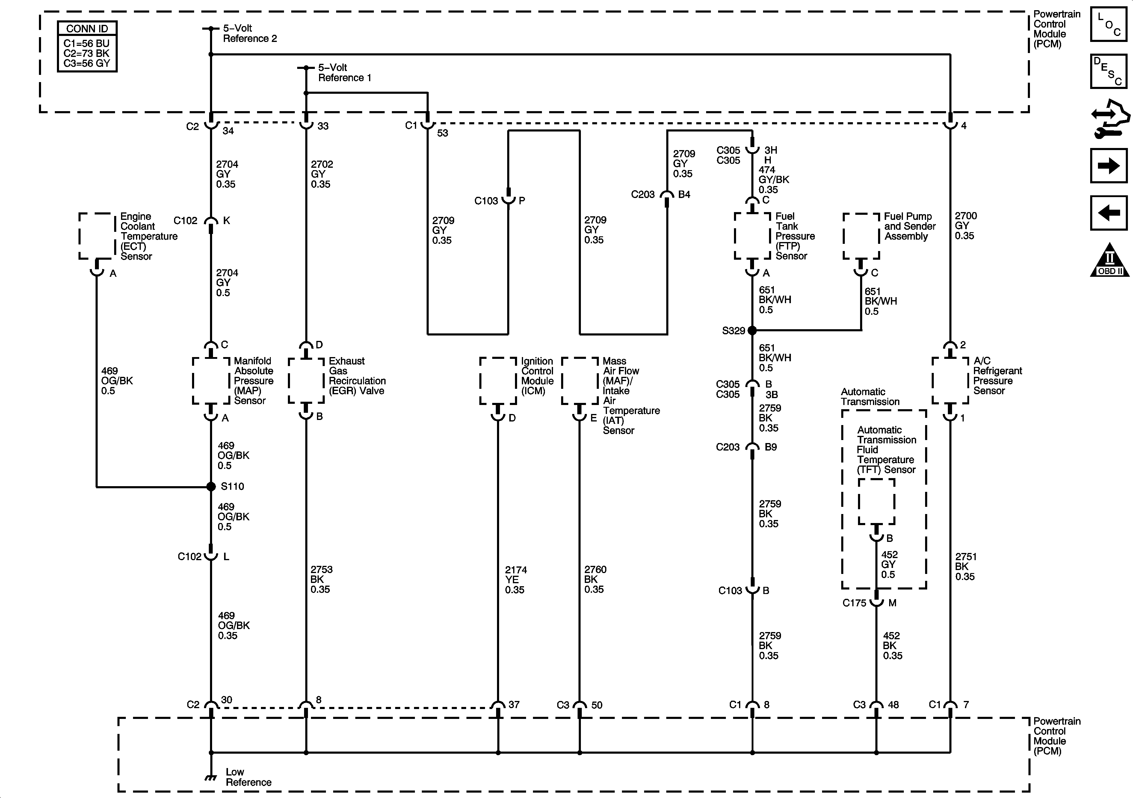
Figure 2:

Engine Data Sensors - 5-Volt and Low Reference

Object Number: 1619477  Size: FS
Master Electrical Component List
Powertrain Control Module Description
Control Module References
Engine Data Sensors-Pressure, Temperature, and VSS
Module Power, Ground, Serial Data, and MIL
Engine Controls Schematic Icons
Figure 3:

Engine Data Sensors - Pressure, Temperature, and VSS
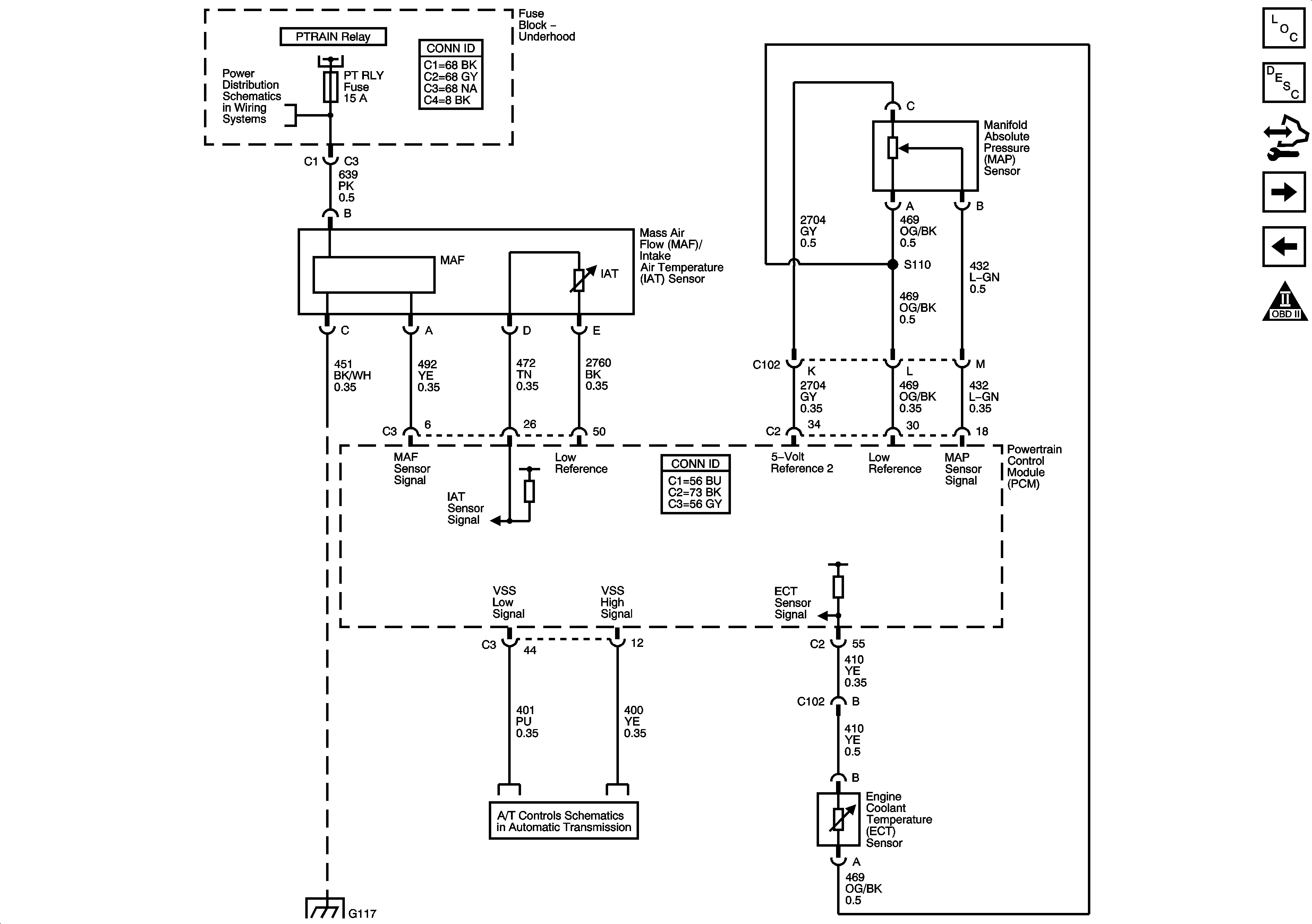

Object Number: 1619480  Size: FS
Master Electrical Component List
Powertrain Control Module Description
Control Module References
Engine Data Sensors-Oxygen Sensors
Engine Data Sensors-5-Volt and Low Reference
Engine Controls Schematic Icons
Module Power, Ground, Serial Data, and MIL
PTRAIN Relay-2 of 2, BTSI, PT RLY, and PT SENSORS Fuses-LX9
ISS, Pressure Control, and VSS-LX9
G117 and G132
Figure 4:

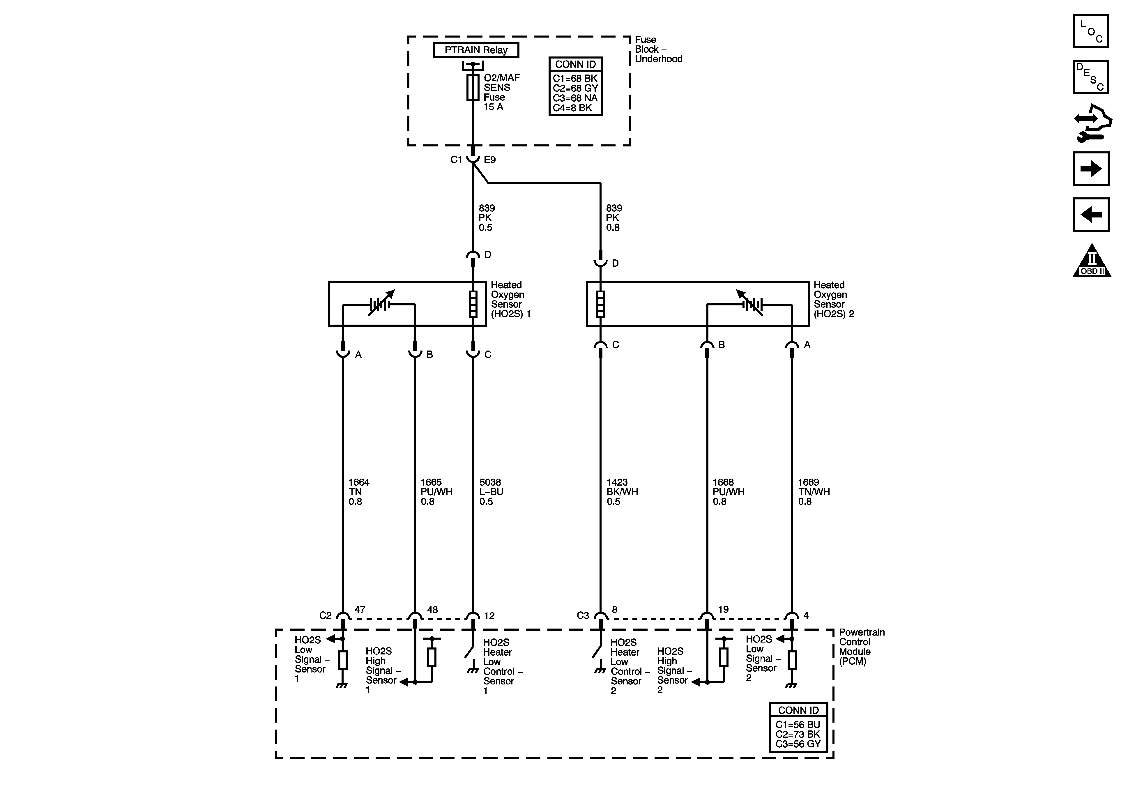
Engine Data Sensors - Oxygen Sensors


Object Number: 1619482  Size: FS
Master Electrical Component List
Powertrain Control Module Description
Control Module References
Throttle Actuator Controls
Engine Data Sensors-Pressure, Temperature, and VSS
Engine Controls Schematic Icons
Module Power, Ground, Serial Data, and MIL
Figure 5:

Engine Data Sensors - Throttle Actuator Controls
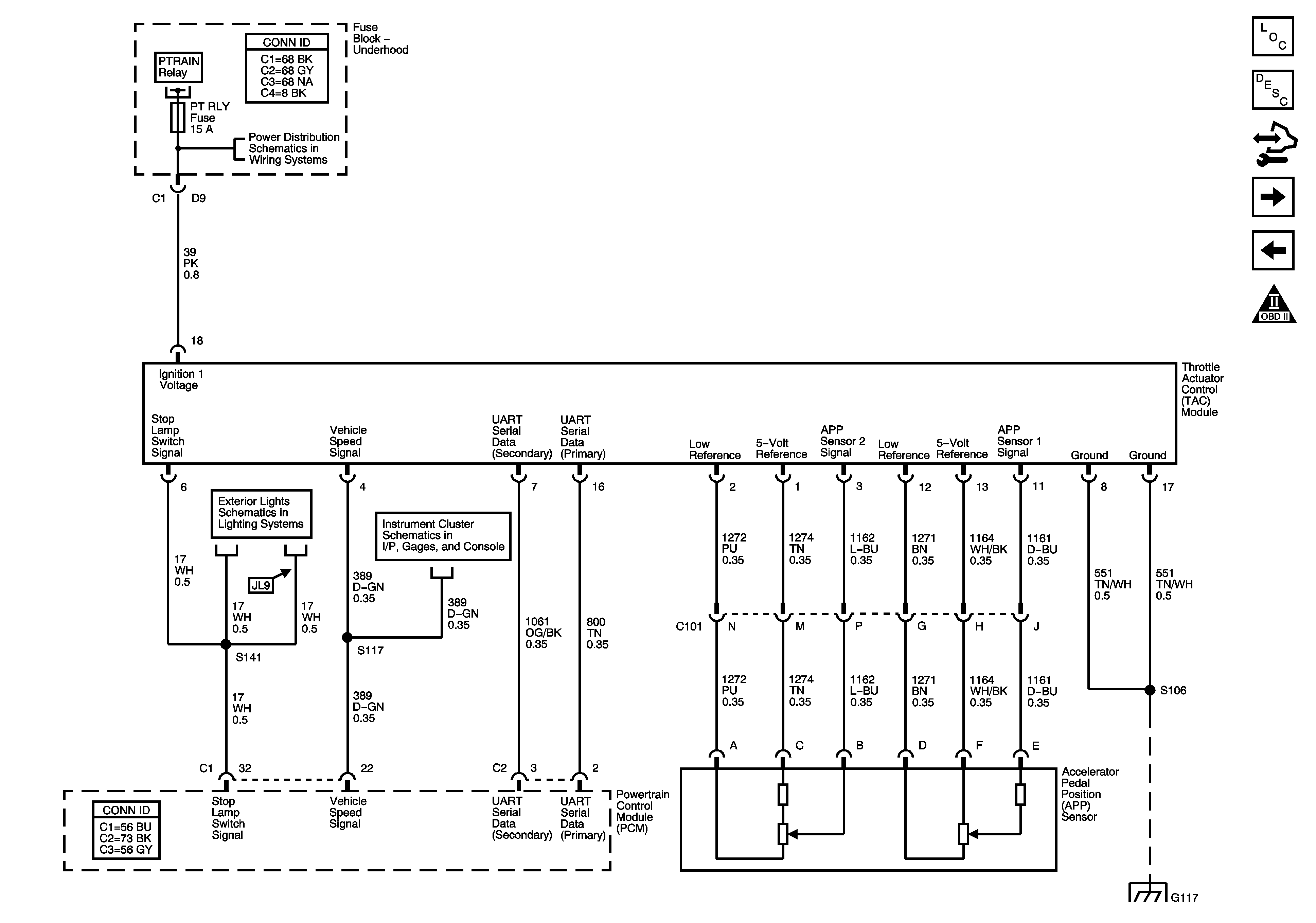

Object Number: 1619485  Size: FS
Master Electrical Component List
Powertrain Control Module Description
Control Module References
Ignition Controls-Ignition System
Engine Data Sensors-Oxygen Sensors
Engine Controls Schematic Icons
Module Power, Ground, Serial Data, and MIL
PTRAIN Relay-2 of 2, BTSI, PT RLY, and PT SENSORS Fuses-LX9
Hazard, Stop, and Turn Signal Lamp Control
Gages-LX9
G117 and G132
Figure 6:

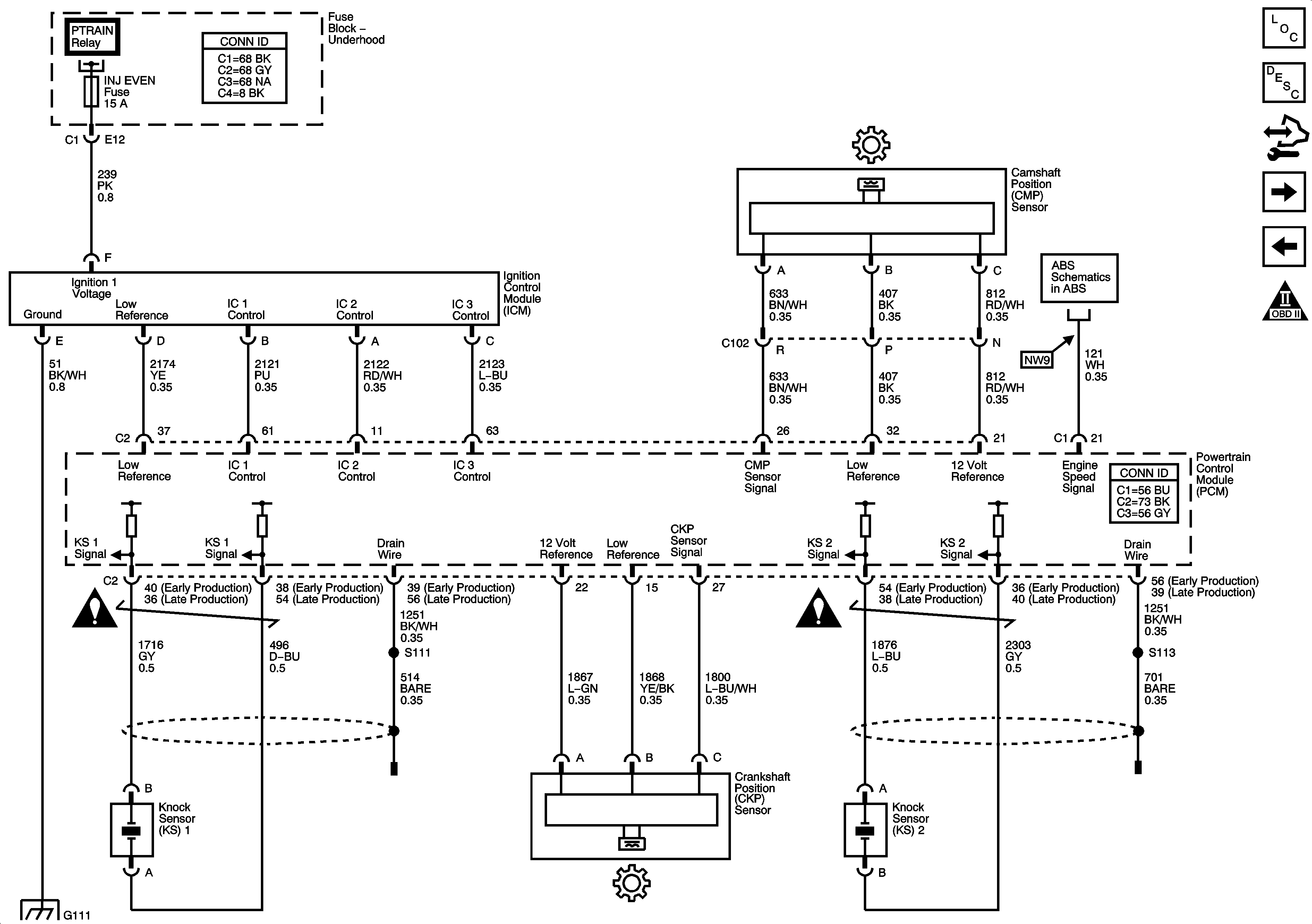
Ignition Controls - Ignition System


Object Number: 1619486  Size: FS
Master Electrical Component List
Powertrain Control Module Description
Control Module References
Fuel Controls-Fuel Pump Controls
Throttle Actuator Controls
Engine Controls Schematic Icons
Module Power, Ground, Serial Data, and MIL
DLC, Indicators, and Traction Control Switch-LX9
Engine Controls Schematic Icons
G100, G111, and G119
Figure 7:

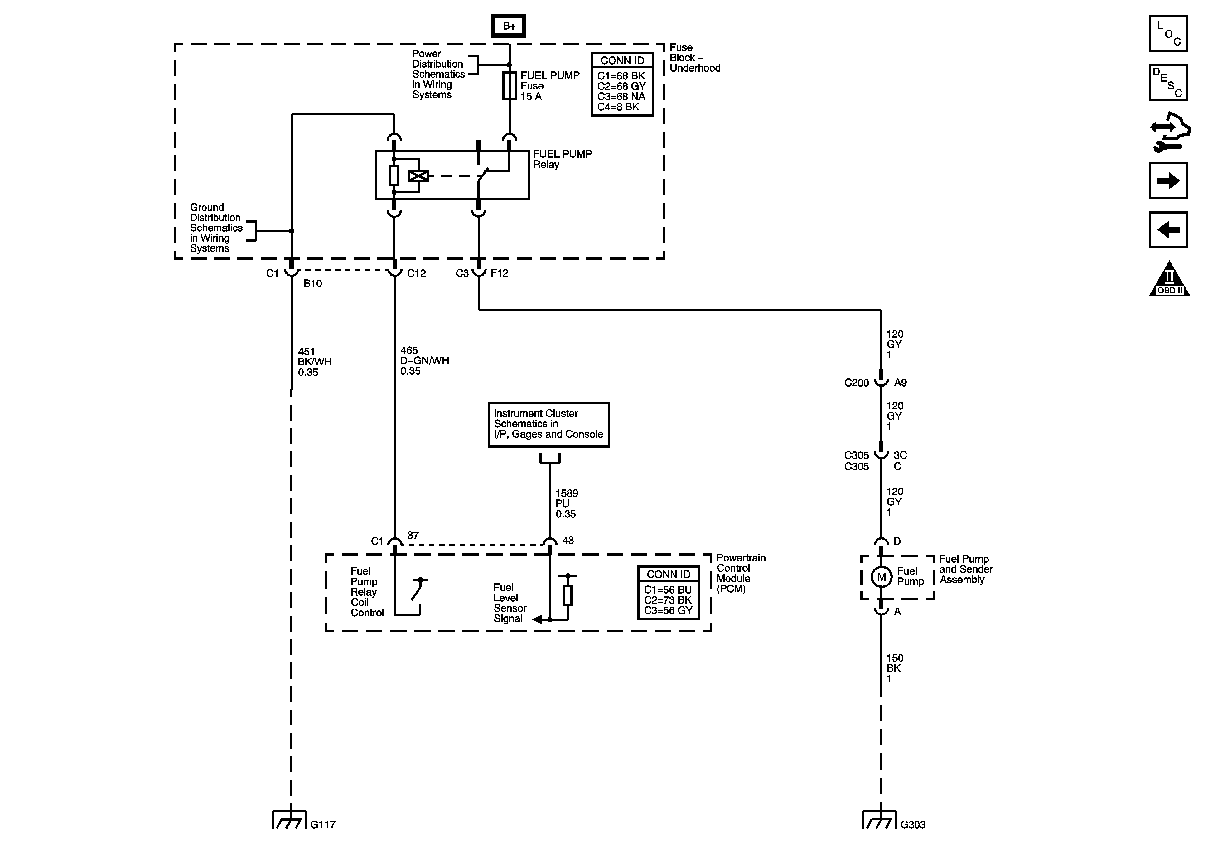
Fuel Controls - Fuel Pump Controls


Object Number: 1619488  Size: FS
Master Electrical Component List
Powertrain Control Module Description
Control Module References
Fuel Controls-Fuel Injectors
Ignition Controls-Ignition System
Engine Controls Schematic Icons
B+ Bus 1 of 2
G117 and G132
Gages-LX9
G117 and G132
G303-1 of 2
Figure 8:

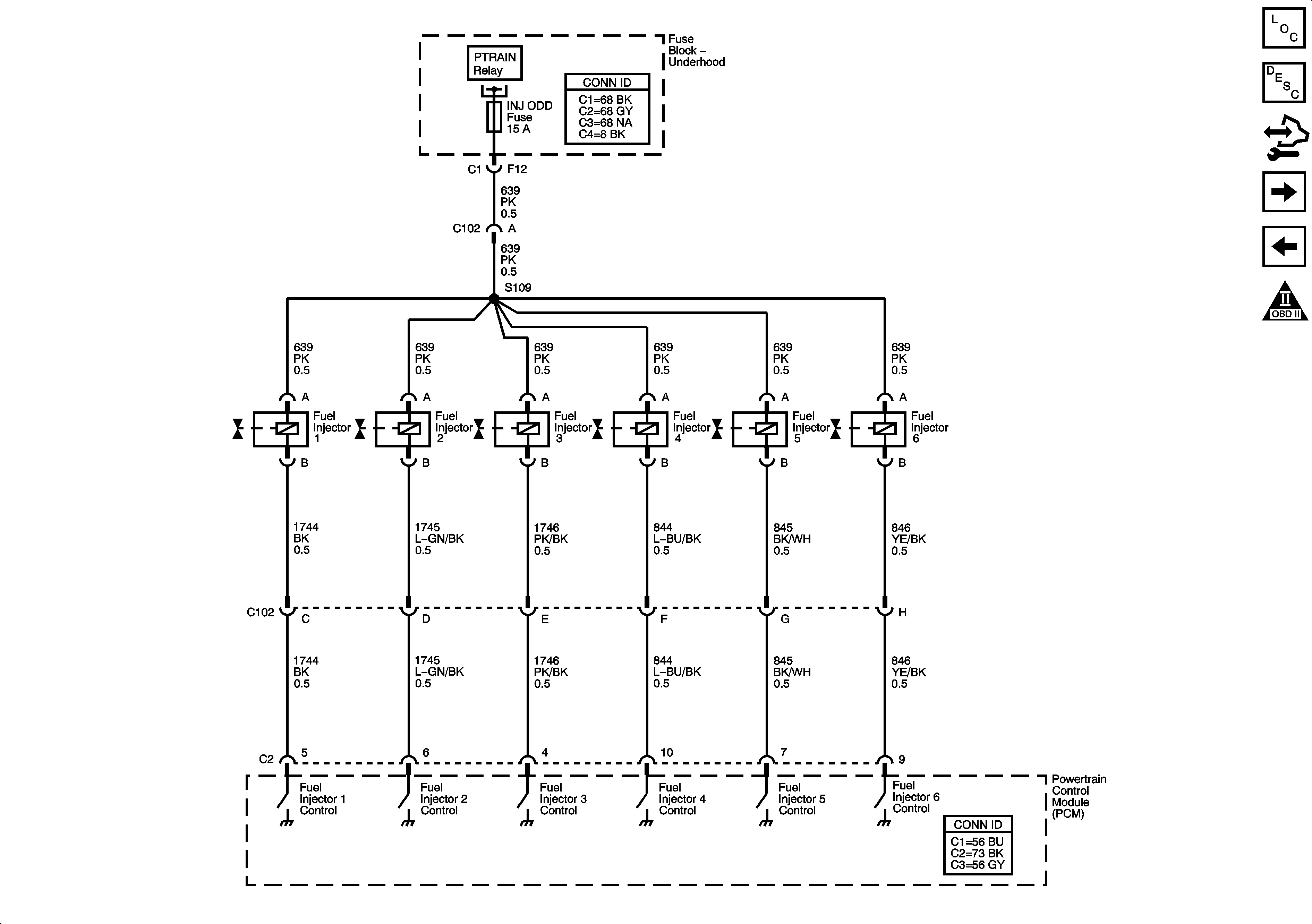
Fuel Controls - Fuel Injectors


Object Number: 1619490  Size: FS
Master Electrical Component List
Fuel System Description
Control Module References
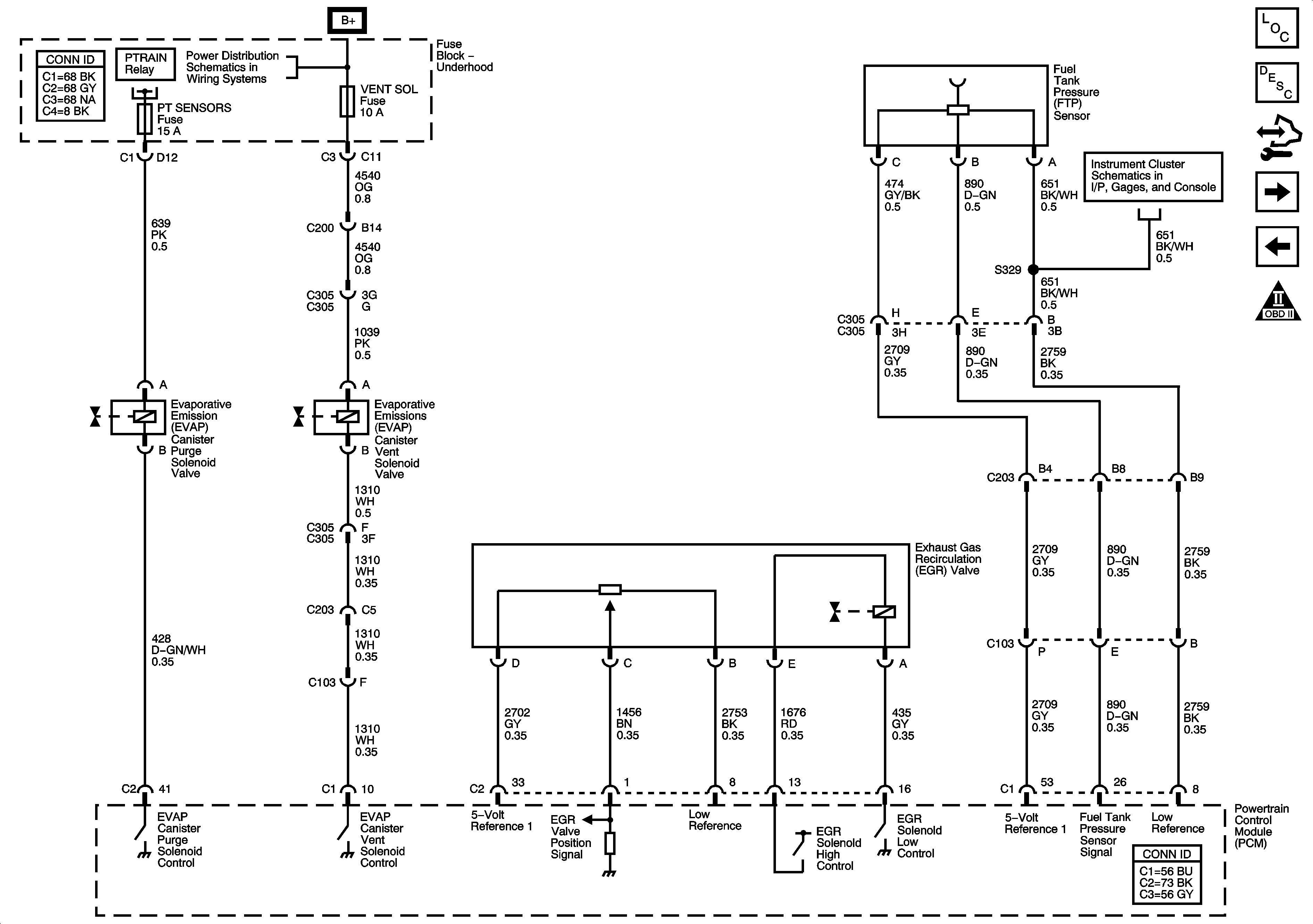
EGR and Fuel Controls-EVAP Controls
Fuel Controls-Fuel Pump Controls
Engine Controls Schematic Icons
Module Power, Ground, Serial Data, and MIL
Figure 9:

EGR and Fuel Controls - EVAP Controls


Object Number: 1619493  Size: FS
Master Electrical Component List
Evaporative Emission Control System Description
Control Module References
Controlled/Monitored Subsystem References
Fuel Controls-Fuel Injectors
Engine Controls Schematic Icons
Module Power, Ground, Serial Data, and MIL
B+ Bus 1 of 2
Gages-LX9
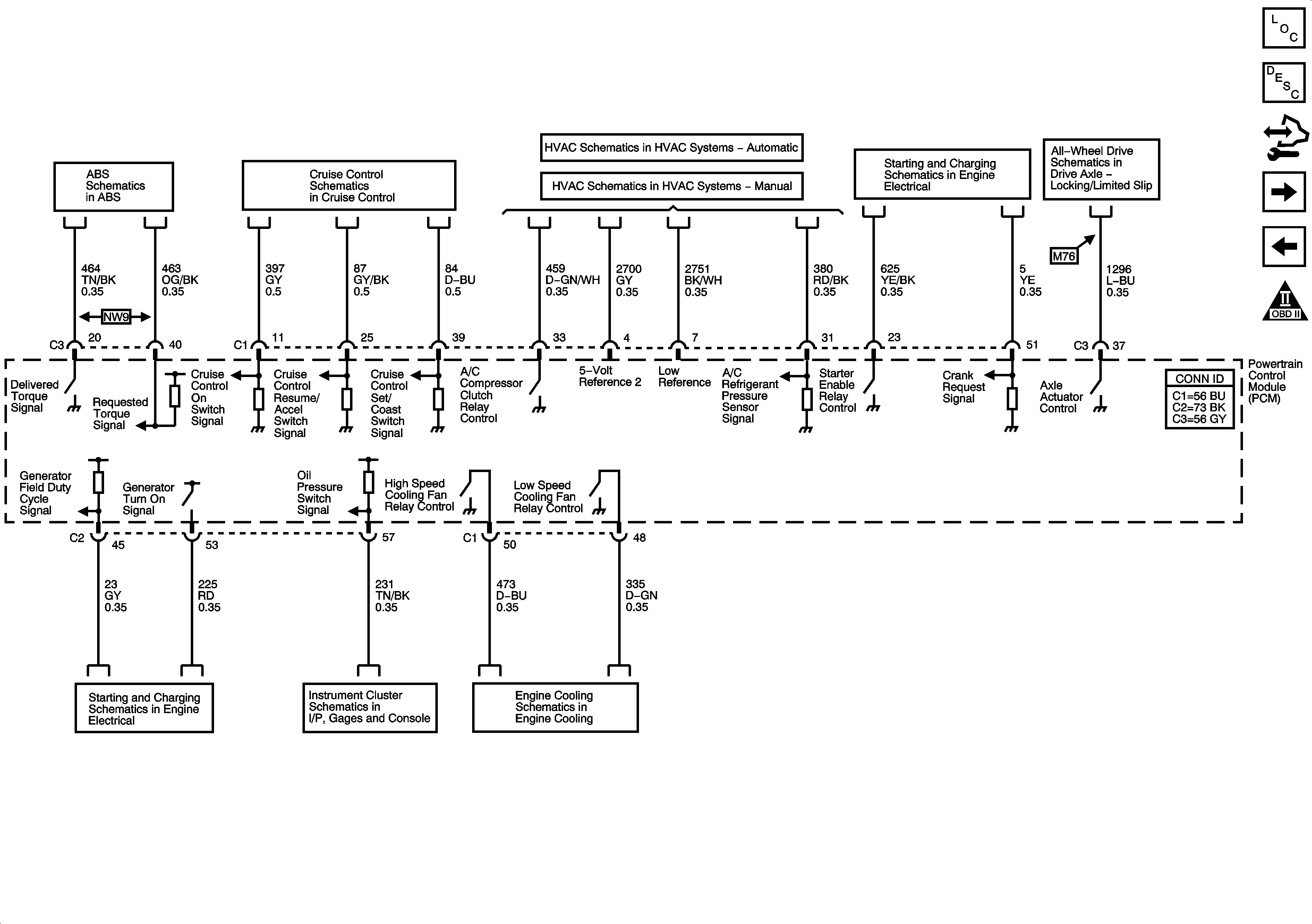
Figure 10:

Controlled/Monitored Subsystem References


Object Number: 1619495  Size: FS
Master Electrical Component List
Powertrain Control Module Description
Control Module References
Transmission Controlled References
EGR and Fuel Controls-EVAP Controls
Engine Controls Schematic Icons
DLC, Indicators, and Traction Control Switch-LX9
LX9
Compressor Controls-LX9
Compressor Controls
Cranking
All-Wheel Drive Schematics
Charging
Engine Oil Sensors and Switches
Fans
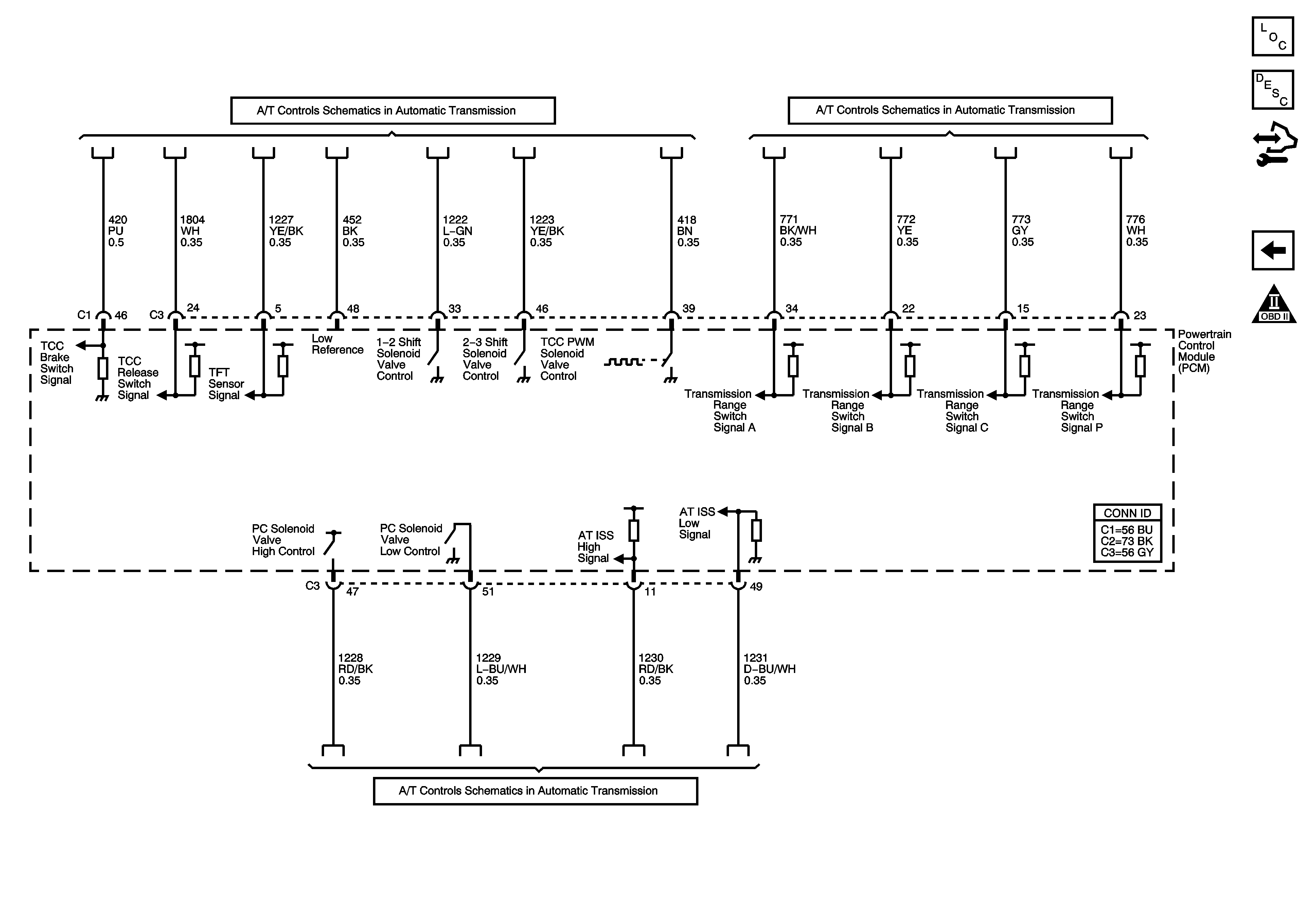
Figure 11:

Transmission Controlled References


Object Number: 1619498  Size: FS
Master Electrical Component List
Powertrain Control Module Description
Control Module References
Controlled/Monitored Subsystem References
Engine Controls Schematic Icons
Shift Solenoids, TCC and TFT-LX9
Internal Mode Switch-LX9
ISS, Pressure Control, and VSS-LX9