GM Service Manual Online
For 1990-2009 cars only
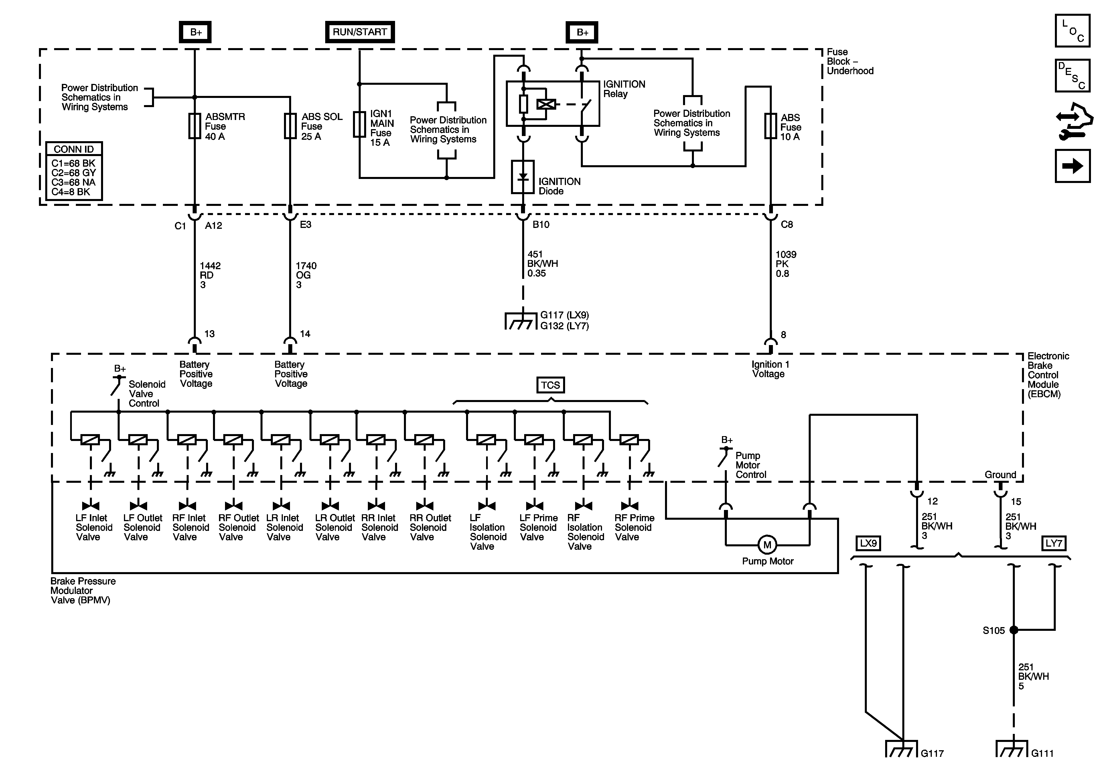
Figure 1:

Ground, Power, Pump, and Solenoid Valves

Object Number: 1619540  Size: FS
Master Electrical Component List
ABS Description and Operation
Control Module References
DLC, Indicators, and Traction Control Switch-LX9
B+ Bus 1 of 2
HVAC/HUD Fuse
B+ Bus 2 of 2
G117 and G132
G117 and G132
G100, G111, and G119
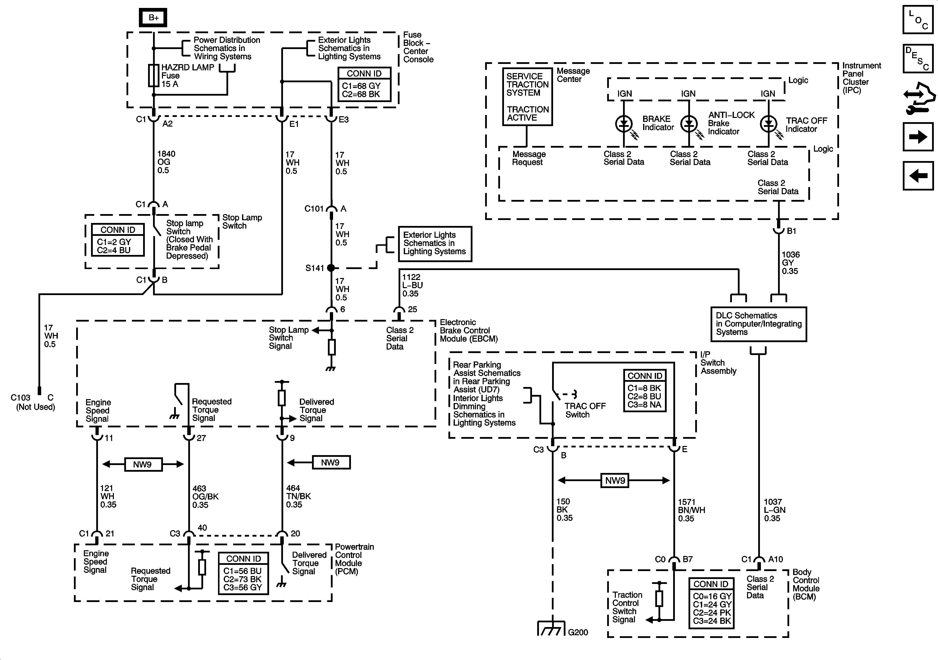
Figure 2:

DLC, Indicators, and Traction Control Switch - LX9

Object Number: 1619541  Size: FS
Master Electrical Component List
ABS Description and Operation
Control Module References
DLC, Indicators, and Traction Control Switch-LY7
Ground, Power, Pump, and Solenoid Valves
BATT 1, HAZRD LAMP, HUD, IPC/HVAC/SEC/RKE, IS LAMP, PK3, RDO and RDO AMP Fuses
Hazard, Stop, and Turn Signal Lamp Control
Enabling, Ground, and Power
I/P and Console Lamps
DLC Schematics
G200
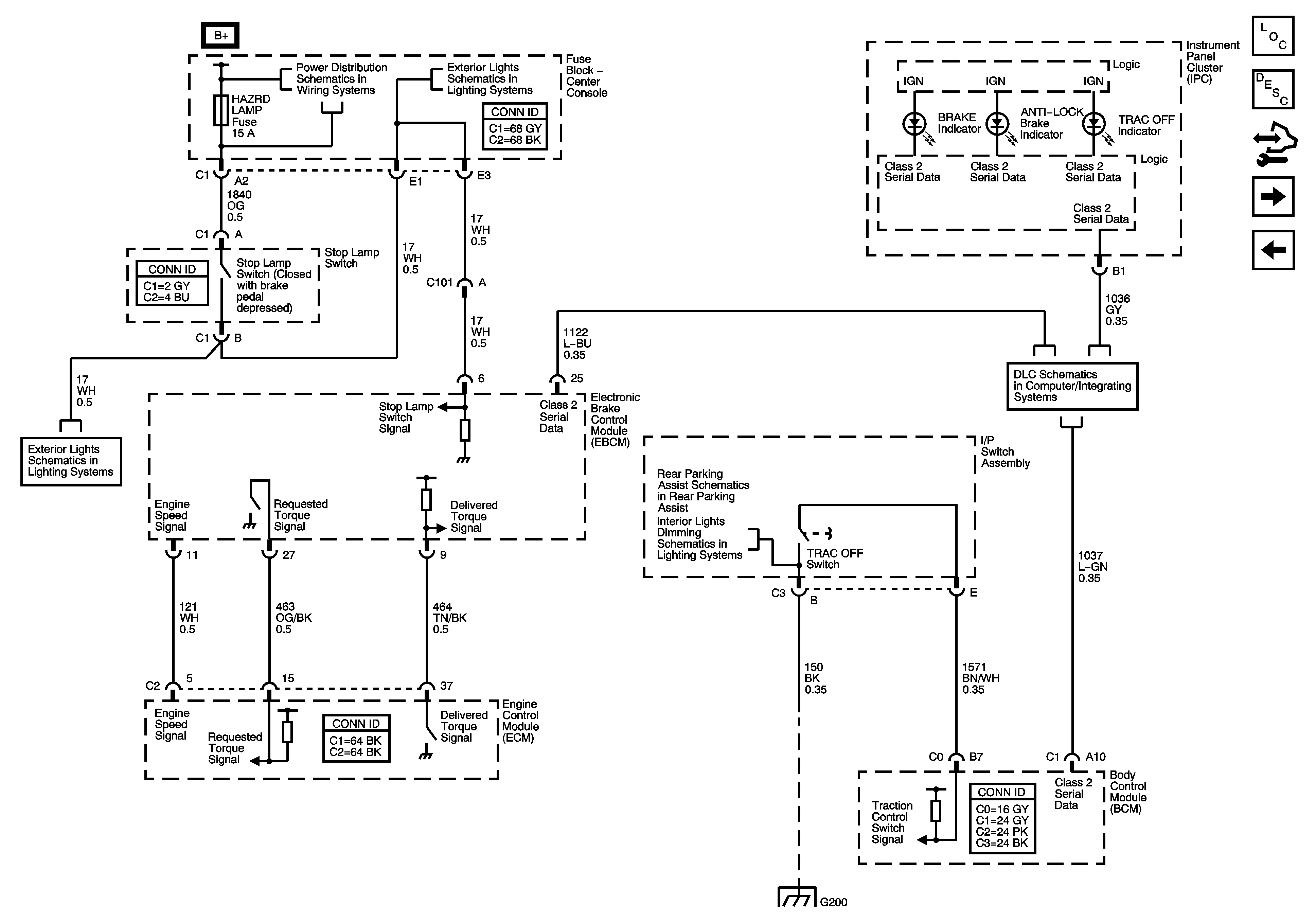
Figure 3:

DLC, Indicators, and Traction Control Switch - LY7

Object Number: 1619542  Size: FS
Master Electrical Component List
ABS Description and Operation
Control Module References
Wheel Speed Sensors
DLC, Indicators, and Traction Control Switch-LX9
BATT 1, HAZRD LAMP, HUD, IPC/HVAC/SEC/RKE, IS LAMP, PK3, RDO and RDO AMP Fuses
Hazard, Stop, and Turn Signal Lamp Control
Enabling, Ground, and Power
I/P and Console Lamps
DLC Schematics
G200
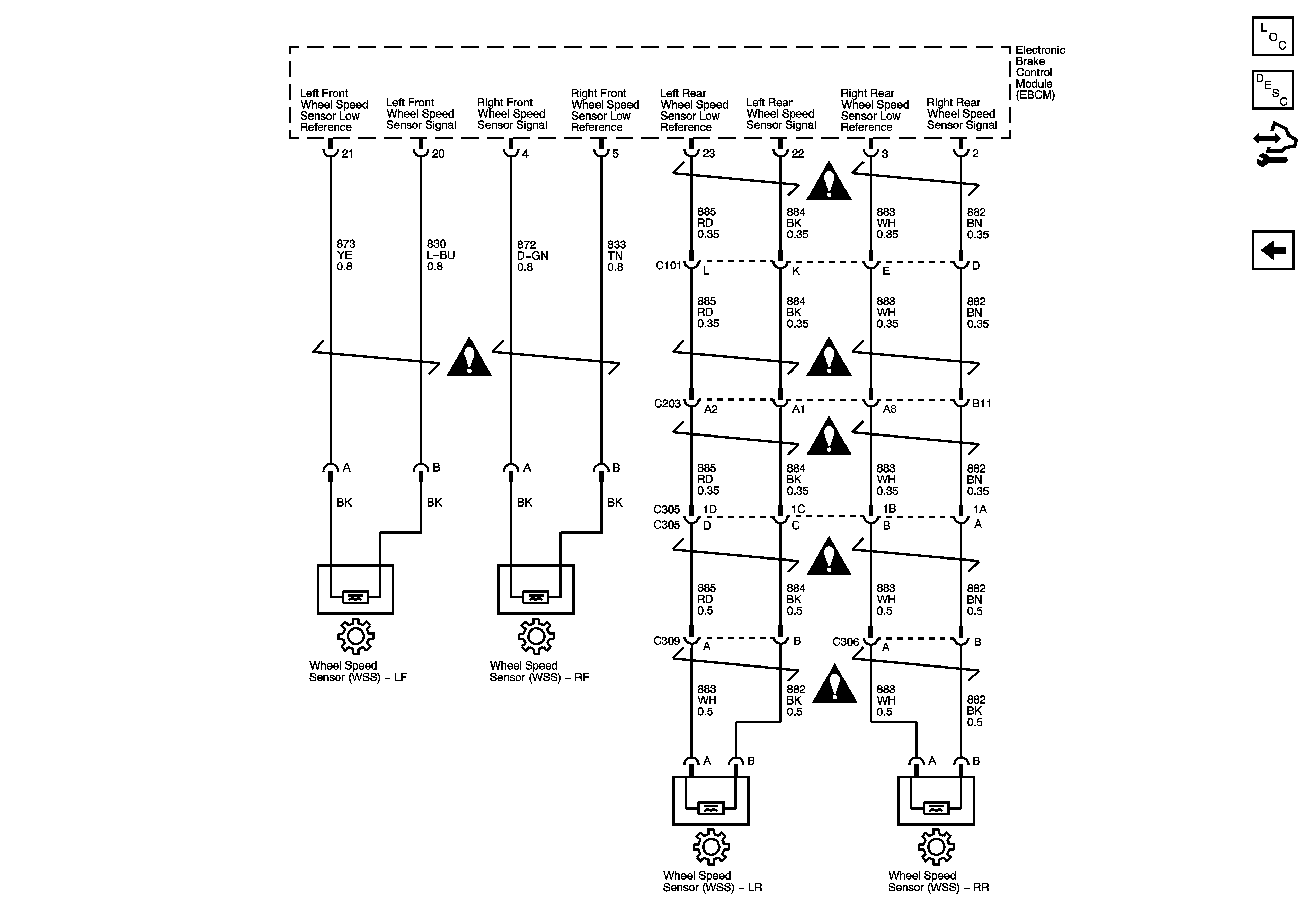
Figure 4:

Wheel Speed Sensors


Object Number: 1619543  Size: FS
Master Electrical Component List
ABS Description and Operation
Control Module References
DLC, Indicators, and Traction Control Switch-LY7
Antilock Brake System Schematic Icons