For 1990-2009 cars only
Removal Procedure
- Disconnect the left and right drive axles from the transaxle. Refer to Front Wheel Drive Shaft Replacement .
- Remove the case extension housing. Refer to Case Extension Replacement .
- Remove the final drive differential. Refer to Final Drive Replacement .
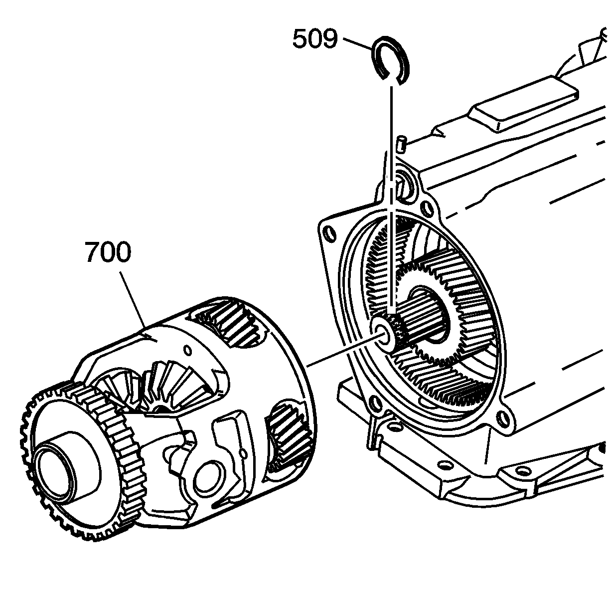
- Use the snap ring pliers in order to remove the compression ring (509) from the output shaft.
- Remove the output shaft through the left wheel opening.
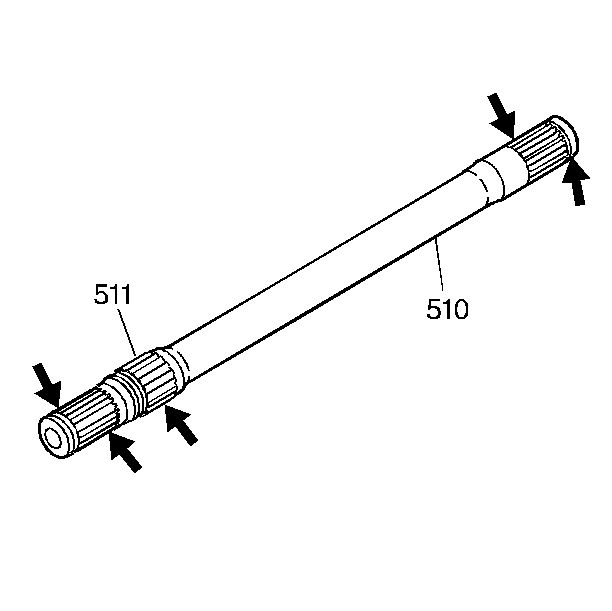
- Inspect the output shaft (510) and the bearing (511) for the following:

Important: Be careful not to damage the bearing on the output shaft.

| • | A cracked or deformed bearing cage |
| • | Damaged bushing journals |
| • | Stripped splines |
| • | A damaged retainer ring groove |
Installation Procedure
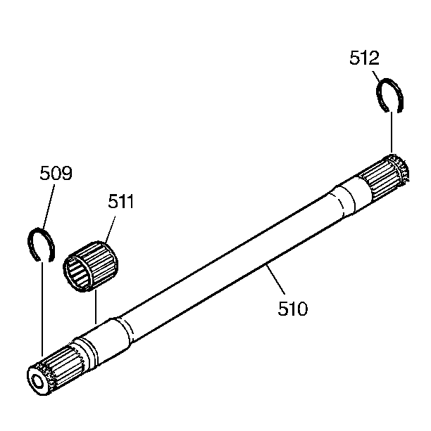
- Install the drive axle retaining ring (509) and the output shaft differential inboard snap ring (512) onto the output shaft (510).
- Install the fourth clutch bearing (511) onto the output shaft (510).
- Hold the final drive differential (700) in place and carefully install the output shaft into the transmission through the left wheel opening and into the differential side gear.
- Install the case extension housing. Refer to Case Extension Replacement .
- Connect the left and right drive axles to the transaxle. Refer to Front Wheel Drive Shaft Replacement .


