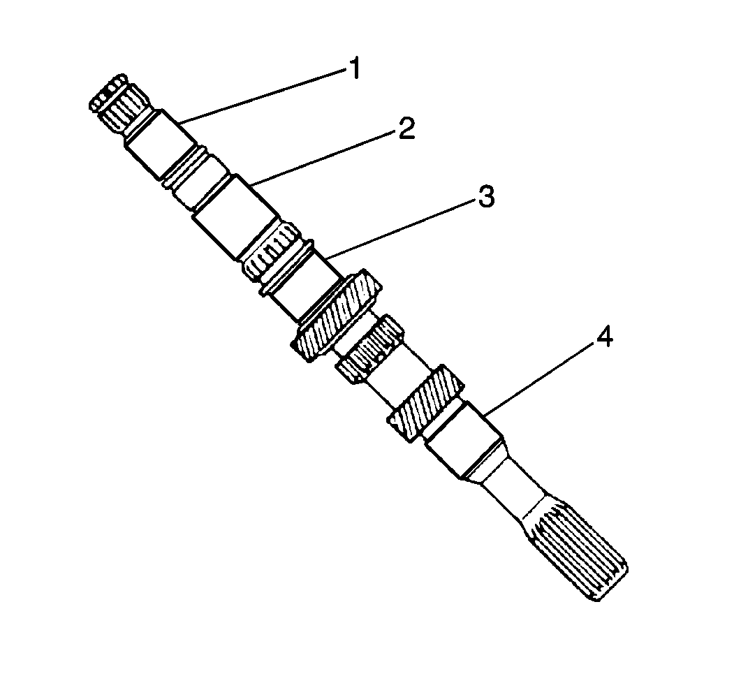
Important: If any of the journal surfaces are under specifications, replace the input shaft.
- Use a
J 26900-2
to measure the outer diameter of the input shaft journal surfaces.
| • | 24.87 mm (0.9791 in) (1) |
| • | 28.97 mm (1.1405 in) (2) |
| • | 30.97 mm (1.2193 in) (3) |
| • | 24.97 mm (0.9831 in) (4) |
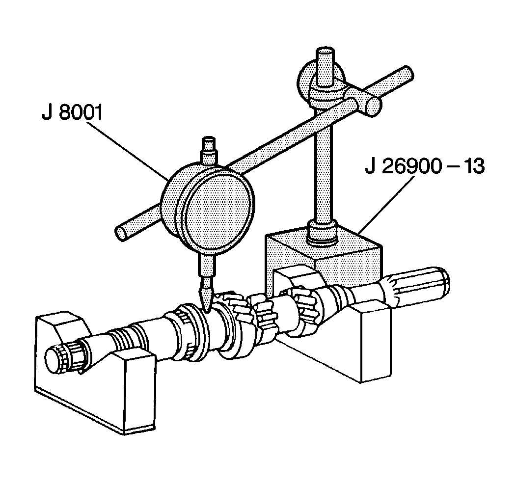
- Use a
J 8001
and a
J 26900-13
to inspect the input shaft runout. If the runout exceeds 0.05 mm (0.0020 in), replace the input shaft.
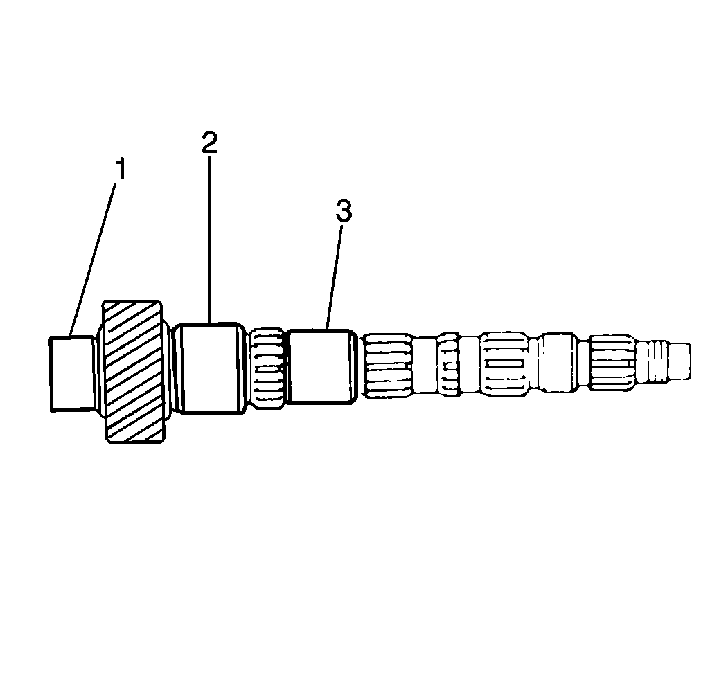
- Use a
J 26900-2
to measure the outer diameter of the
output shaft journal surfaces (1, 2, 3).
Important: If any of the journal surfaces are under specifications, replace the output shaft.
| 3.1. | 32.97 mm (1.2980 in) (1) |
| 3.2. | 37.97 mm (1.4949 in) (2) |
| 3.3. | 31.97 mm (1.2587 in) (3) |
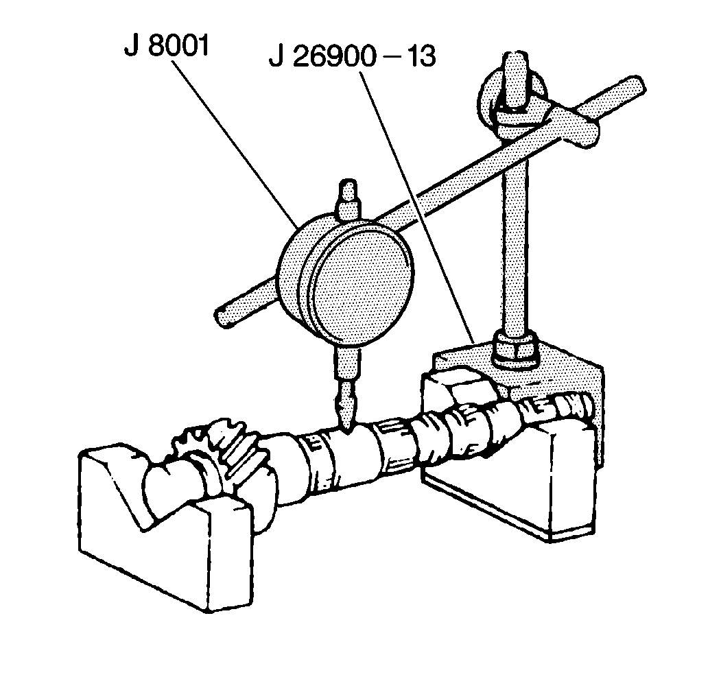
- Use a
J 8001
and a
J 26900-13
to inspect the output shaft runout. If the runout exceeds 0.05 mm (0.0020 in), replace the output shaft.
- Inspect the synchronizer rings by turning and pushing on them in order to test the braking action.
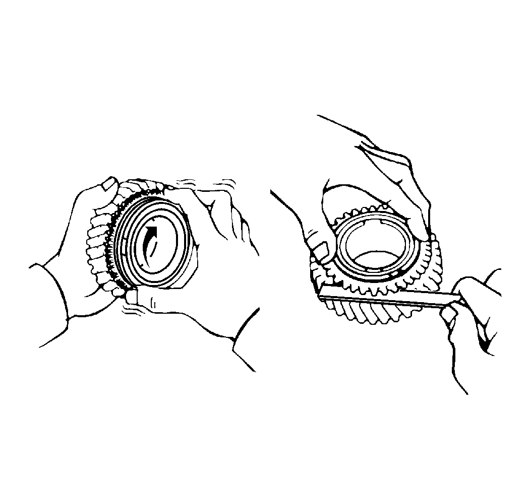
- Inspect the synchronizer ring clearance by measuring between the back of the synchronizer ring and the gear spline end. If clearance
is less than 0.6 mm (0.024 in), replace the synchronizer ring.
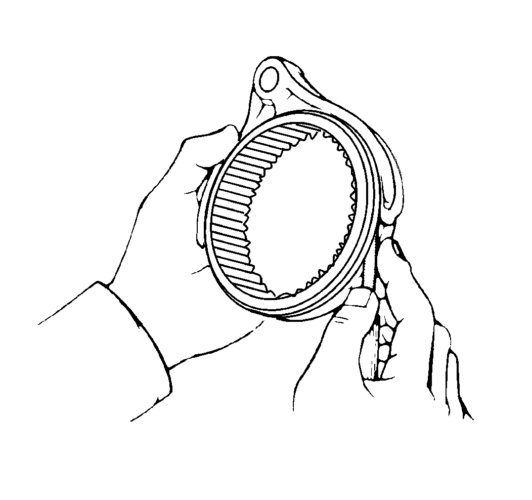
- Use a feeler gage to measure the clearance between the hub sleeve and the shift fork. If the clearance
exceeds 1.0 mm (0.0039 in), replace the shift fork or replace the hub sleeve.
- Remove the input shaft front seal.
- Remove the bearing lock plate.
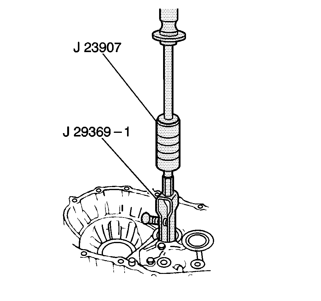
- Inspect the input shaft front bearing. If you must replace the bearing, use a
J 23907
and a
J 29369-1
.
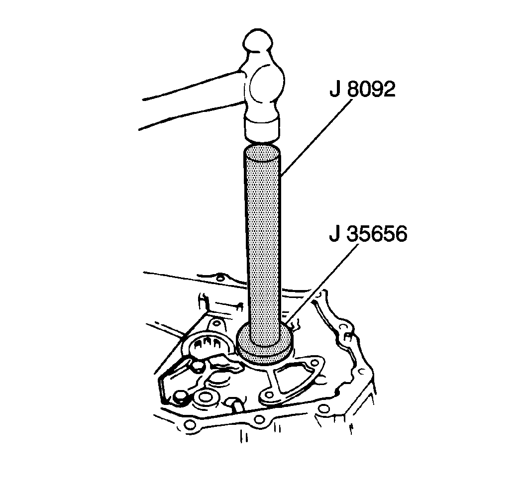
- Use a
J 8092
and a
J 35656
to install the bearing.
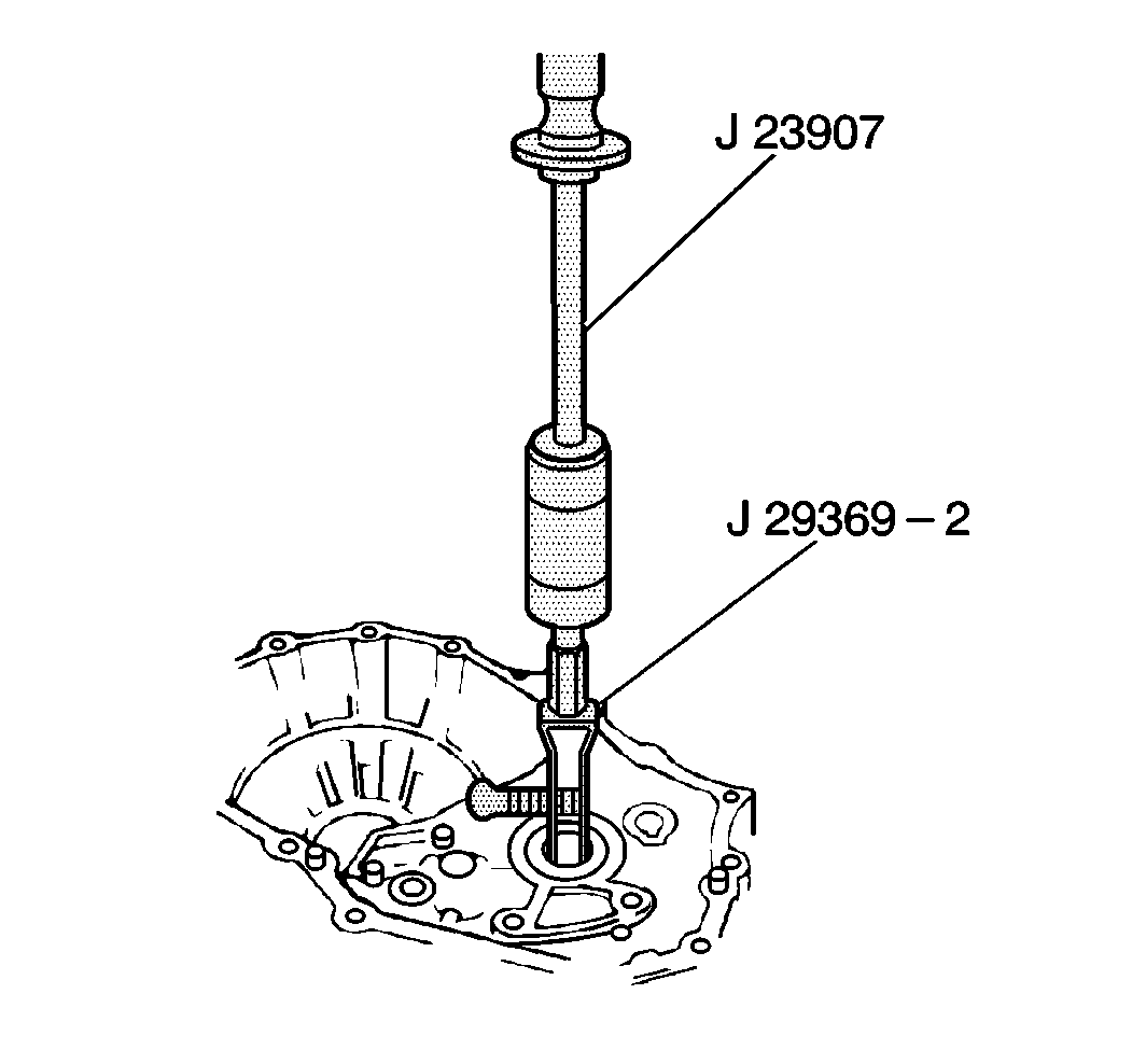
- Inspect the output shaft front bearing. If you must replace the bearing, use a
J 23907
and a
J 29369-2
.
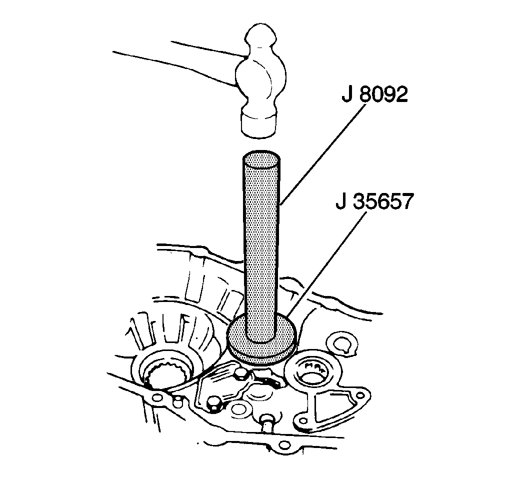
- Install the bearing use a
J 8092
and a
J 35657
.
- Use a
J 33183
to install the input shaft front seal. Lightly coat the seal lip with GM P/N 1051344.
Notice: Use the correct fastener in the correct location. Replacement fasteners
must be the correct part number for that application. Fasteners requiring
replacement or fasteners requiring the use of thread locking compound or sealant
are identified in the service procedure. Do not use paints, lubricants, or
corrosion inhibitors on fasteners or fastener joint surfaces unless specified.
These coatings affect fastener torque and joint clamping force and may damage
the fastener. Use the correct tightening sequence and specifications when
installing fasteners in order to avoid damage to parts and systems.
- Install the bearing lock plate.
Tighten
Tighten the bearing lock bolts to 11 N·m (97 lb in).
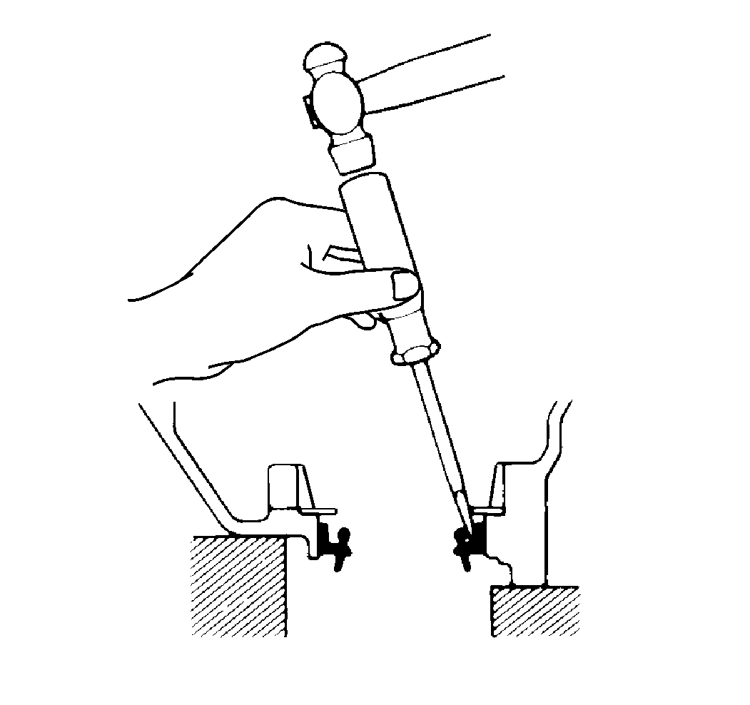
- Inspect the RH differential oil seal and inspect the LH differential oil seal.
If replacement is necessary, remove the seal with a screwdriver.
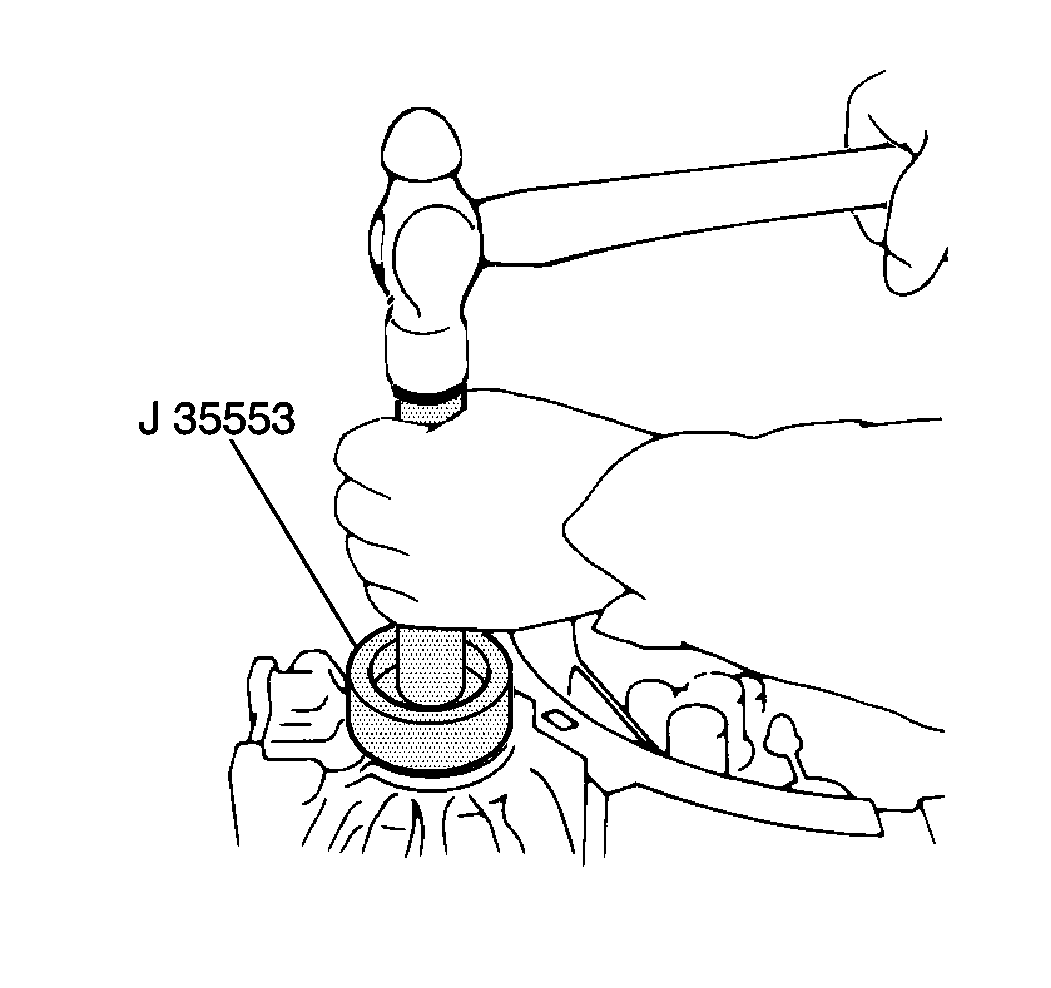
- Use a
J 35553
to install a new seal flush with the
case surface. Lightly coat the seal lip with GM P/N 1051344.
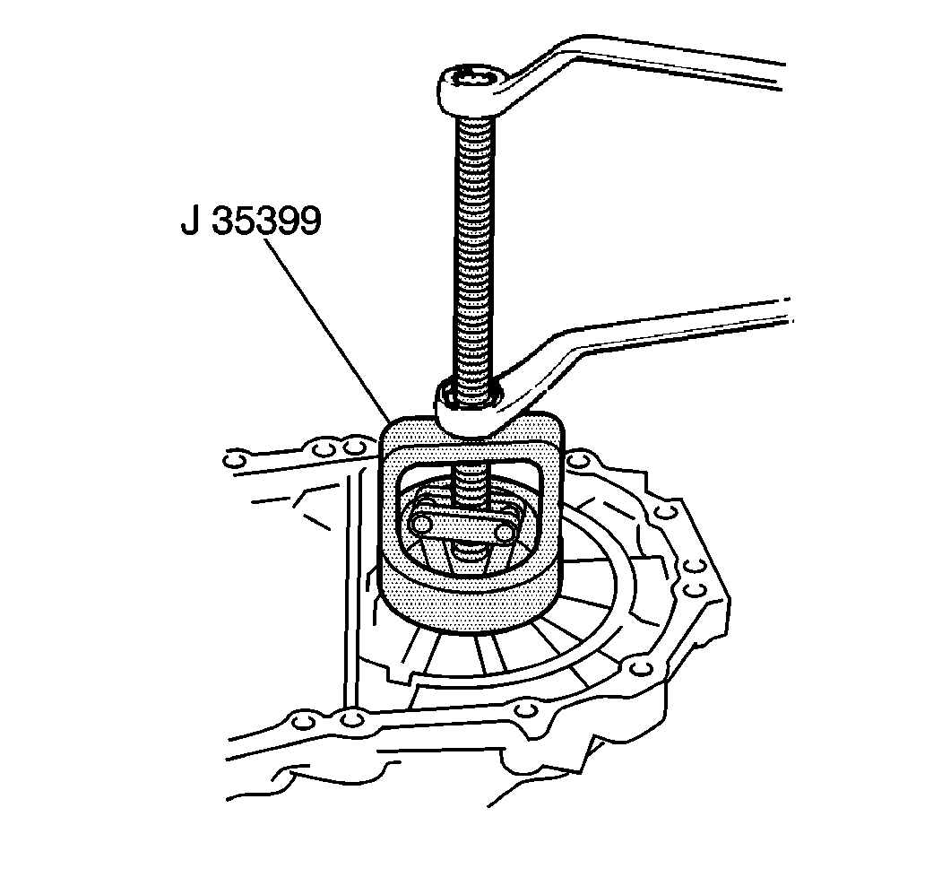
- Inspect the RH differential bearing cap and the LH differential bearing cap. If replacement is necessary,
use a
J 35399
to remove the bearing caps.
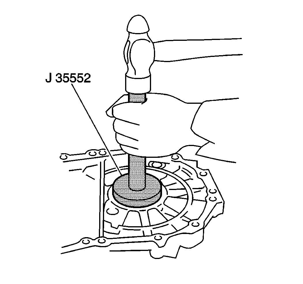
- Use a
J 35552
to install the bearing caps.
- Inspect the control shaft cover seal. If replacement is necessary use the following procedure:
| 20.1. | Remove the old seal with a screwdriver. |
| 20.3. | Coat the lip of the seal with GM P/N 1051344. |
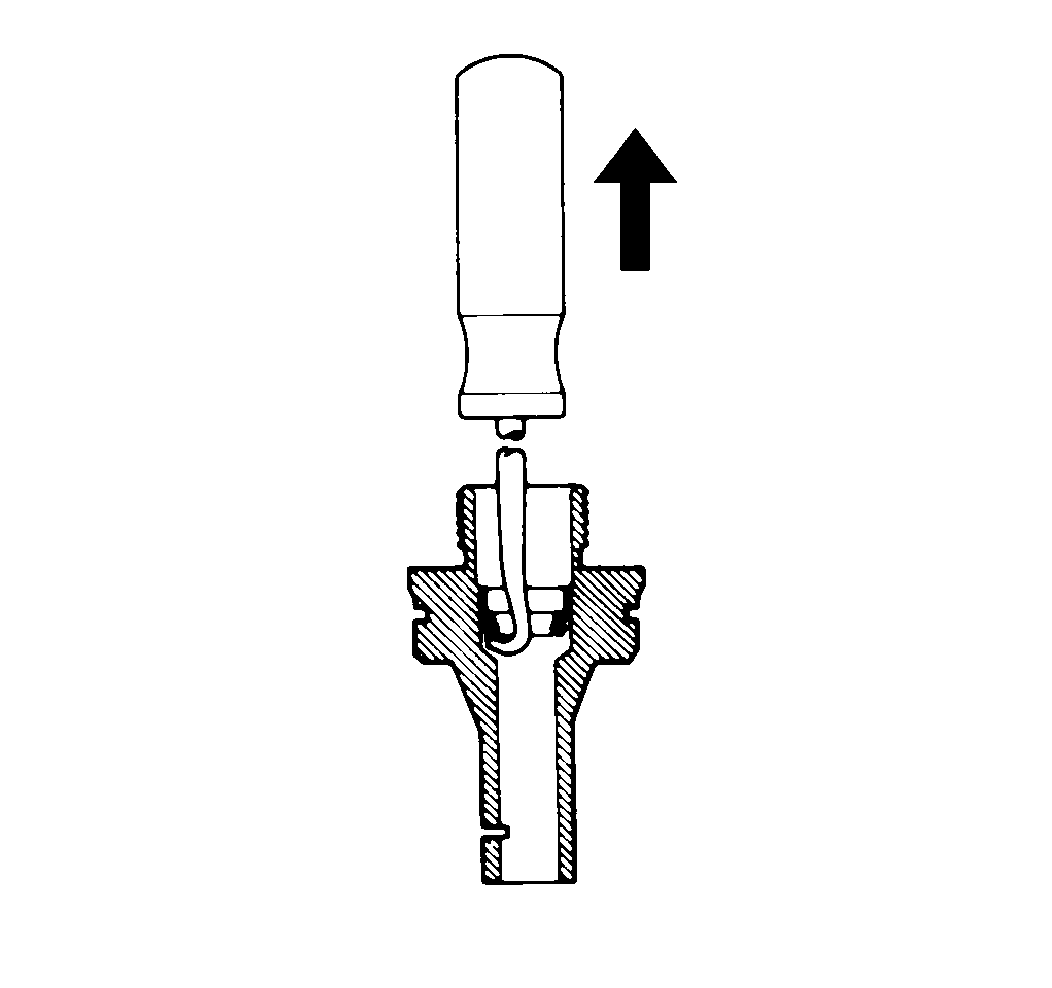
- Inspect the speedometer seal. If replacement is necessary remove the old seal.
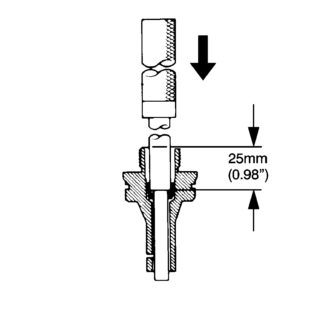
- Coat the new seal with GM P/N 1051344.
- Install the seal to a depth of 25 mm (0.98 in).
- Inspect the reverse restrict pin. If replacement is necessary, perform the following procedure:
| 24.1. | Remove the reverse restrict holder. |
| 24.2. | Using a pin punch and a hammer, driver out the slotted spring pin. |
| 24.3. | Replace the reverse restrict pin. |
| 24.4. | Driver in the slotted pin. |


