DOOR UPPER TRIM ASSEMBLY REMOVAL AND REPAIR

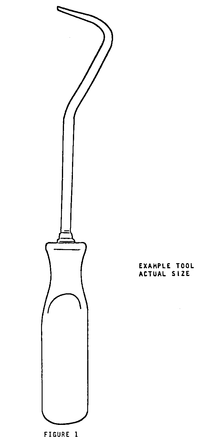
The following procedure has been developed to improve the removal of the door upper trim assembly and also prevent accidental damage to the trim pad front and rear retaining embossments. The tool shown in Figure 1, and referred to in Step 6, can be made from an ice pick or similar tool. The revised removal procedure is as follows:
REMOVAL
1. Lower door window.
2. Remove door inside locking rod knob.
3. Remove door pull strap, where present.
4. Remove door inside remote control handle escutcheon attaching screw.
5. Insert tool J-24595B or equivalent between door inner panel and trim assembly and disengage retaining clips at side of upper trim panel.
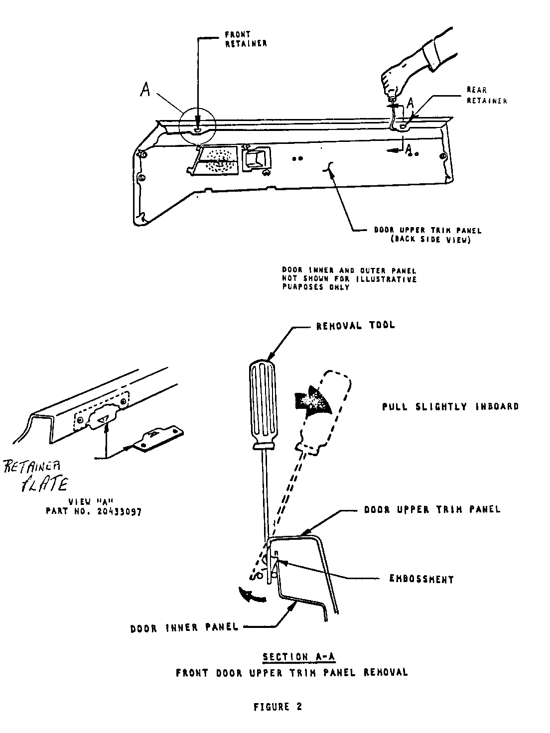
6. Using tool shown in Figure 1, insert tip of tool behind trim pad rear retaining embossment as shown in Figure 2. Rotate tool inboard to disengage pad from rear retainer.
7. Repeat Step #6 at front retaining embossment.
INSTALLATION
1. Before installing door trim, check that all trim retainers are securely installed to trim assembly and are not damaged. Replace damaged trim retainers as required.
2. Check door belt trim support retainers to determine if they are broken. If retainer(s) is broken, use belt trim support retainer plate (Part No. 20433097) to repair door belt trim support. Retainer plate should be secured to the door trim assembly by drilling two (2) holes through plate and belt trim support and securing plate to support with pop-rivets as shown in view "A", Figure 2.
The belt trim support retainer plate is available as a service part and may be used to repair any door trim pad that is of similar design.
3. To install door trim assembly, pull door inside handle inboard; then position door trim to inner panel, inserting handle through hole in door trim panel.
4. Install trim pad over locking rod knob, then firmly engage upper trim pad embossments with front and rear retainers.
5. Position door trim to inner panel so trim retainers are aligned with attaching holes in inner panel and tap retainers into holes with palm of hand or a clean rubber mallet.
6. Install all previously removed hardware items.
To help prevent damage in the future, the thickness of the current belt trim support has been increased from 2.5 to 3.0mm.
Warranty Information
Labor Operation use door trim pad R & R
Labor Time Trim pad R & R plus .2 hr. for one or both sides
Trouble Code 92


General Motors bulletins are intended for use by professional technicians, not a "do-it-yourselfer". They are written to inform those technicians of conditions that may occur on some vehicles, or to provide information that could assist in the proper service of a vehicle. Properly trained technicians have the equipment, tools, safety instructions and know-how to do a job properly and safely. If a condition is described, do not assume that the bulletin applies to your vehicle, or that your vehicle will have that condition. See a General Motors dealer servicing your brand of General Motors vehicle for information on whether your vehicle may benefit from the information.
