NO 3RD GEAR AND/OR NO DRIVE OR REVERSE

TRANSMISSION APPLICATIONS: 4T60, F-7
SUBJECT: NO 3RD GEAR, AND/OR NO DRIVE OR REVERSE - CENTRE GEARBOX DISTRESS DIAGNOSIS TIPS
VEHICLE APPLICATIONS: 1984-91 A,C,E,H,K,W,V CAR
Bulletin Covers:
Centre gearbox distress diagnosis tips - all 1984-91 HYDRA-MATIC 4T60 and THM F-7 transaxles. Centre gearbox distress in a HYDRA- MATIC 4T60 or THM F-7 transaxle may result in one of the following conditions:
1. No 3rd gear due to a distressed 3rd roller clutch cage. Also, slips in 3rd gear or no 3rd gear.
2. No drive or reverse due to a distressed input sprag.
3. Distressed 3rd and input clutch fiber and reaction (steel) plates.
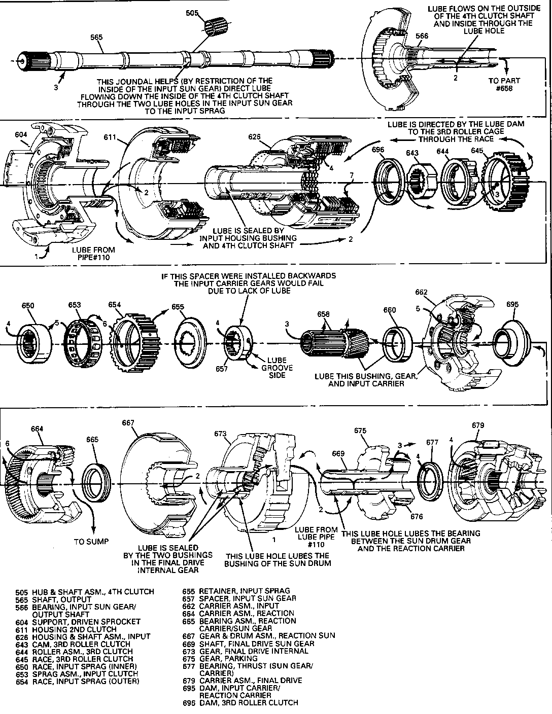
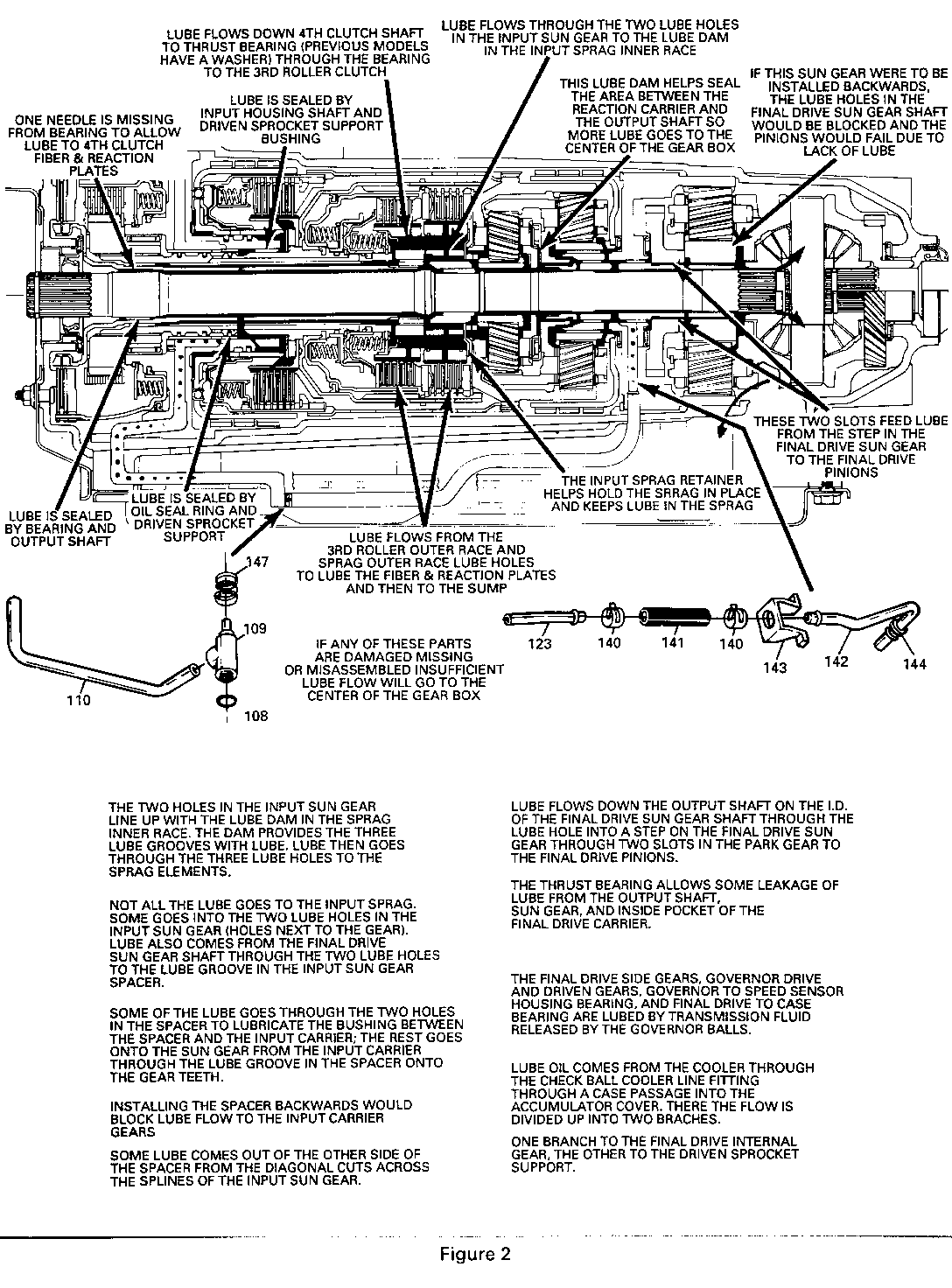
Many changes were implemented to help reduce centre gearbox distress. This Bulletin will discuss them and reference bulletins already published on previous changes and what components should be inspected during an overhaul. Also, some other helpful tips and information about lubrication flow have been added. Refer to Figures 1 and 2.
Several aftermarket publications have been written concerning different ways to modify the centre gear box. Some of the modifications include grinding slots, lining up the lube holes differently, and greatly increasing the fluid level. DO NOT ATTEMPT THESE PROCEDURES! These publications were written to supposedly improve the performance of the centre gear box, but instead the modifications can cause durability concerns or the procedures are not necessary.
1. Chances have been made to the 3rd roller clutch which will imprcle its durability. Revisions have been made to the lube holes on the outside race. Four of the lube holes have been eliminated. When the lube holes are eliminated, the rollers are less likely to cock or skew when overrunning. When the rollers cock or skew, excessive heat is created Reference Product Service Bulletin 90-7440-113.
1A. To increase the lubrication to the 3rd roller clutch assembly, a 3rd roller clutch dam was added and the input housing shaft I.D. 4th clutch shaft seal was eliminated. This change occurred for the 1985-1/2 model year. Reference pages 1-7 and 1-8 in the Hydra-Matic 440-T4 Product Update book (1985 through 1985 model year).
2. New Output Shaft With A Single Path Bearing: The new output shaft and bearing allows more lubrication fluid to flow to the centre of the gearbox. Reference Product Service Bulletin 90-7440-113.
3. New 10 Plate 3rd Clutch Assembly For SOP 1989: The 10 plate clutch assembly, compared to the previous 8 plate clutch assembly, is for higher torque engine applications and also helps eliminate heat build-up due to numerous repeat manual Lo engagements at speeds around 35 MPH. Reference Product Service Bulletin #89-7440-101.
4. End Plays: If the final drive has too much clearance, this will allow the final drive sun gear to move away from the thrust bearing in the final drive. This will allow too much lube fluid to leak out from the final drive sun gear shaft - with the correct final drive end play, the sun gear would block most of the lube fluid from escaping from the sun gear shaft. If the input housing has too much clearance, this would allow too much lubrication fluid to leak out between the input housing thrust bearing and 3rd roller clutch cam. Some leakage is designed in, but too much due to worn, damaged, missing bushings, too much end play or incorrectly installed parts could cause a durability concern. Reference the lubrication circuit fluid flow description, as shown in Figure 1.
5. The final drive sun gear lube groove must face towards the parking gear to allow adequate lubrication flow to the final drive pinions. The final drive sun gear shaft has lubrication holes in the shaft that feed fluid into the step in the sun gear, then through the two slots in the parking gear to the final drive pinions - if the final drive sun gear was installed backwards, the holes in the final drive sun gear shaft would be blocked, not allowing fluid to lubricate the final drive pinions.
6. Check lube pipes for correct installation and any damage (plastic cracked, pipes bent, etc.). Ensure the lube pipe retainer is in the proper position. A mispositioned or damaged component will leak lubrication fluid into the bottom pan instead of directing the fluid to the centre of the gearbox. While bolting down the accumulator cover, inspect the position of the lube oil pipe retainer - reposition if cocked.
7. Fluid Foaming Due To Overfilling Or Incorrect Thermo Element Height: If the fluid level is too high, the moving parts will churn the fluid, causing the oil to foam. This will cause many durability concerns including damage to the centre of the gear box. An incorrect thermo element height will cause the fluid level to be inaccurate (either too low or too high) when the fluid is up to operating temperatures. Too low a fluid level will cause air to be sucked into the filter, and too high a level will cause fluid foaming due to churning. Check the height with thermo element height setting tool, J-34094-A.
8. 4th clutch hub and shaft assembly should have one needle missing from the inside of the bearing cage for oil flow to the 4th clutch fiber and reaction plates.
9. Cooler Flow Test - Oil cooler for the transaxle that is located in the radiator and the oil-to-air cooler (optional) that is connected in series with the radiator transaxle oil cooler: Correct flow is two quarts of fluid per 30 seconds. Also, it must be flushed; refer to Labour Time Guide for Labour Operations that must have the transaxle oil cooler flushed.
10. Input Housing To 3rd Roller Cam Thrust Washer Replace With A Needle Bearing: Reference Product Service Bulletin #89-7440-105 for details about interchangeability and past model service.
11. The lube dam must be installed on most 1986 and newer models between the input and reaction carriers. Leaving a worn, damaged or missing lube dam will allow too much lubrication fluid to leak into the bottom pan. Reference Product Service Bulletin #87-7440-105.
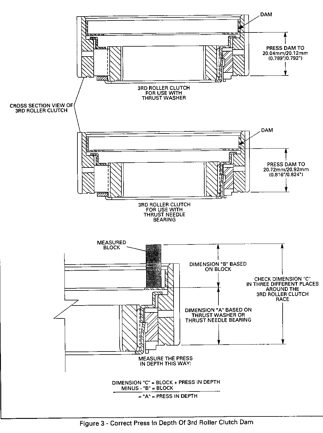
IMPORTANT: When reassembling a 3rd roller clutch, ensure that the lube dam is pressed into the proper depth. If the 3rd roller clutch is mated to the thrust needle bearing instead of the washer, then:
- press the dam to a depth of 20.72/20/92mm (0.816/0.824") as measured from the bottom side (sprag side) of the outside race to the wide flat edge of the dam as shown in Figure 3.
If using the thrust washer, press the dam (on models so equipped) to a depth of 20.04/20.12mm (0.789/0.792") as measured from the bottom side (sprag side) of the outside race to the wide flat edge of the dam as shown in Figure 3.
NOTICE: Measure the press in depth for the dam as shown in Figure 3. Measuring from the top of the 3rd roller clutch race to the dam will be inaccurate because all the machining of the 3rd roller clutch race is based on the opposite side (side that mates to the input sprag). If the dam is pressed in too far or not far enough, it could rub on the 3rd roller clutch cage or the snap ring that retains the 3rd clutch return spring and create excess heat to distress the cage of the 3rd roller clutch.
12. Line Pressures: Lubrication fluid is proportional with line pressures. If the line pressure is below specification, then lubrication fluid flow would be inadequate. Check the line pressure as outlined in the Product Service Bulletin #90-7440-114 for further details about vacuum modulator diagnosis.
13. Check converter clutch regulator valve for proper operation, binding, sediment or damage, etc. This valve controls the flow of lubrication - when the torque/viscous converter clutch (TCC/ VCC) is applied, mainline lubrication fluid from the pump pressure regulator is routed past the torque converter directly to the cooler; when TCC/VCC is not applied, the fluid is routed through the converter, then to the cooler. If the valve is damaged, a new valve is included in service package #8646934 - use only the converter clutch regulator valve from this package.
SERVICE PARTS INFORMATION:
PART NUMBER DESCRIPTION USAGE ----------- ------------------- ------------- 8646934 Package, V.B. Spacer Plate Conv. All 84-91 4T60 Cl. Regulator Valve and Spring Models
IMPORTANT: USE ONLY THE CONV. CL. REGULATOR VALVE FROM THE PACKAGE


General Motors bulletins are intended for use by professional technicians, not a "do-it-yourselfer". They are written to inform those technicians of conditions that may occur on some vehicles, or to provide information that could assist in the proper service of a vehicle. Properly trained technicians have the equipment, tools, safety instructions and know-how to do a job properly and safely. If a condition is described, do not assume that the bulletin applies to your vehicle, or that your vehicle will have that condition. See a General Motors dealer servicing your brand of General Motors vehicle for information on whether your vehicle may benefit from the information.
