SERVICE MANUAL UPDATE REAR BRAKE CALIPER OVERHAUL

MODELS AFFECTED: 1986-1988 RIVIERAS AND 1988 REATTAS
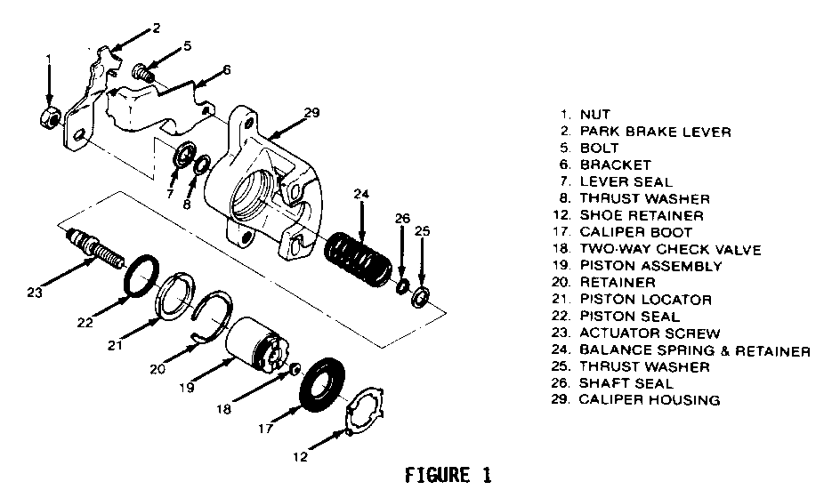
When overhauling the rear calipers on 1986-1988 Rivieras and 1988 Reattas, using overhaul kit, Part Number 18012689, a new procedure should be used. The copper thrust washer, Item 25 in Figure 1, is larger than the original thrust washer. The original thrust washer O.D. is 22.5mm and the service replacement thrust washer 25.4mm. To prevent an interference condition between the thrust washer and balance spring retainer use the procedure below rather than Section 5B7 of the 1986-1987 Service Information Manual. The 1988 Final Fdition Service Information Manual will be revised to include this procedure.
Assembly Procedure (Figure 1):
1. Bleeder valve to 13 N-m (110 in. lb.).
2. Bracket (6), if removed, with bolt (5) to 43 N-m (31 ft. lb.).
3. Lubricate new piston seal (22) and caliper housing (29) bore with clean brake fluid.
* Piston seal (22) into caliper bore groove. * Make sure seal is not twisted.
4. Lubricate new piston locator (21) with clean brake fluid. Install piston locator (21) on piston (19) using installer J-35588-2 and pilot J-35588-1.
5. Position thrust washer (25) on actuator screw (23) with copper side of washer toward piston (19) and grayish side toward caliper housing (29).
6. Position lubricated shaft seal (26) on actuator screw (23).
7. Install actuator screw (23) along with thrust washer and shaft seal into caliper housing (29).
8. Position balance spring (24) into piston (19) recess.
9. Install lubricated piston (19) with balance spring (24) into lubricated bore of caliper (29).
* Push piston into caliper so that locator (21) is past retainer groove in caliper bore. * Turn actuator screw (23) as necessary to allow piston to move toward the bottom of the caliper bore.
10. Install retainer (20) using retaining ring pliers.
11. Install lubricated boot (17) onto piston (19) with inside lip of boot in piston groove and boot fold toward outboard side of piston. Push piston assembly to bottom of caliper bore.
12. Position lubricated antifriction washer (8) and lever seal (7) over the end of actuator screw (23).
* Sealing bead on lever seal (7) should be against caliper housing (29).
13. Install lever (2) on actuator screw (23). Rotate lever away from stop slightly and hold while installing nut (1) to 41-54 N-m (30-40 lb. ft.), then rotate lever to contact stop.
14. Seat boot (17) in caliper housing (29) counterbore using J-35587.
* After seating boot, lift inner edge next to piston (17) and press out any trapped air. Boot must lay flat.

General Motors bulletins are intended for use by professional technicians, not a "do-it-yourselfer". They are written to inform those technicians of conditions that may occur on some vehicles, or to provide information that could assist in the proper service of a vehicle. Properly trained technicians have the equipment, tools, safety instructions and know-how to do a job properly and safely. If a condition is described, do not assume that the bulletin applies to your vehicle, or that your vehicle will have that condition. See a General Motors dealer servicing your brand of General Motors vehicle for information on whether your vehicle may benefit from the information.
