SERVICE MANUAL UPDATE RIVIERA LANDAU CAP ASSEMBLY

SERVICE MANUAL UPDATE
MODELS AFFECTED: 1988 RIVIERA LANDAU CAP ASSEMBLY ----------------
Following are procedures describing removal and installation of the vinyl fabric covered cap assembly, C04 landau option. See Body Manual, Section 8D for vinyl repair procedures. See Section 2 for information on stationary glass and molding installation.
Vehicles having a sunroof option must have the sunroof unit closed and covered for protection prior to installation of the landau cap assembly. This will prevent rivet chips and other debris from causing damage to sunroof parts.
NOTICE: Tape protective covers on all surfaces of vehicle adjacent to cap to prevent paint damage. Also, when drilling out rivets, u!e a drill stop or other method to prevent drill bit from going more than 1/2" deep. This will prevent damage to inner roof line.
Remove or Disconnect:
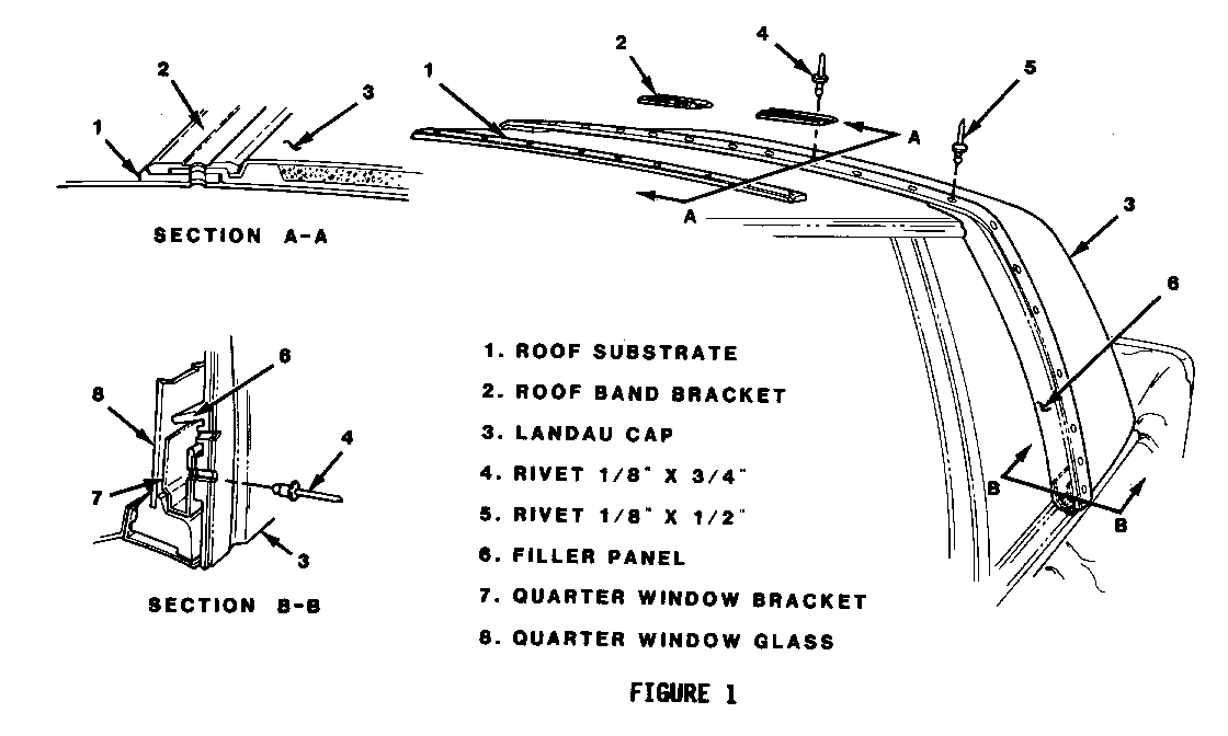
1. Metal escutcheon at top center of roof band (Figure 1).
2. Roof band molding across forward edge of landau cap assembly by drilling out one (1) rivet at top center holding each molding half, using drill stop as indicated before (Figure 1).
3. Pull out clips holding sides of each molding half to cap assembly and slide roof band moldings outward to remove from roof band brackets on top of landau cap (Figure 1).
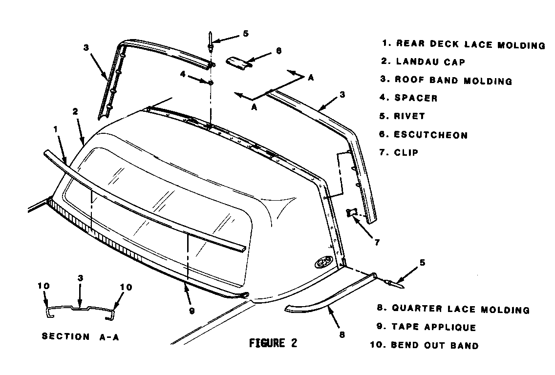
4. Using a drill stop, all rivets holding cap, sides and beltline of cap assembly to roof panel (Figure 2) (if same cap is to be reinstalled, quarter filler panels and roof band molding brackets on cap do not have to be removed from assembly as they will be used again).
5. Quarter lace moldings by first drilling out one rivet securing forward edge of each molding, using drill stop, and then pulling off (Figure 1).
6. Rear deck vinyl lace molding (if it is to be replaced) by pulling off the deck lid surface (Figure 1).
NOTICE: If a new landau cap assembly is to be installed, old rivet holes should not be used, if possible, to avoid a loose fit of new cap to vehicle. Therefore, run a piece of masking tape across roof, forward of landau cap assembly and also under the belt line. Mark locations of existing rivets in old cap on tape before drilling them out. These location marks will be used for reference later when installing new cap assembly.
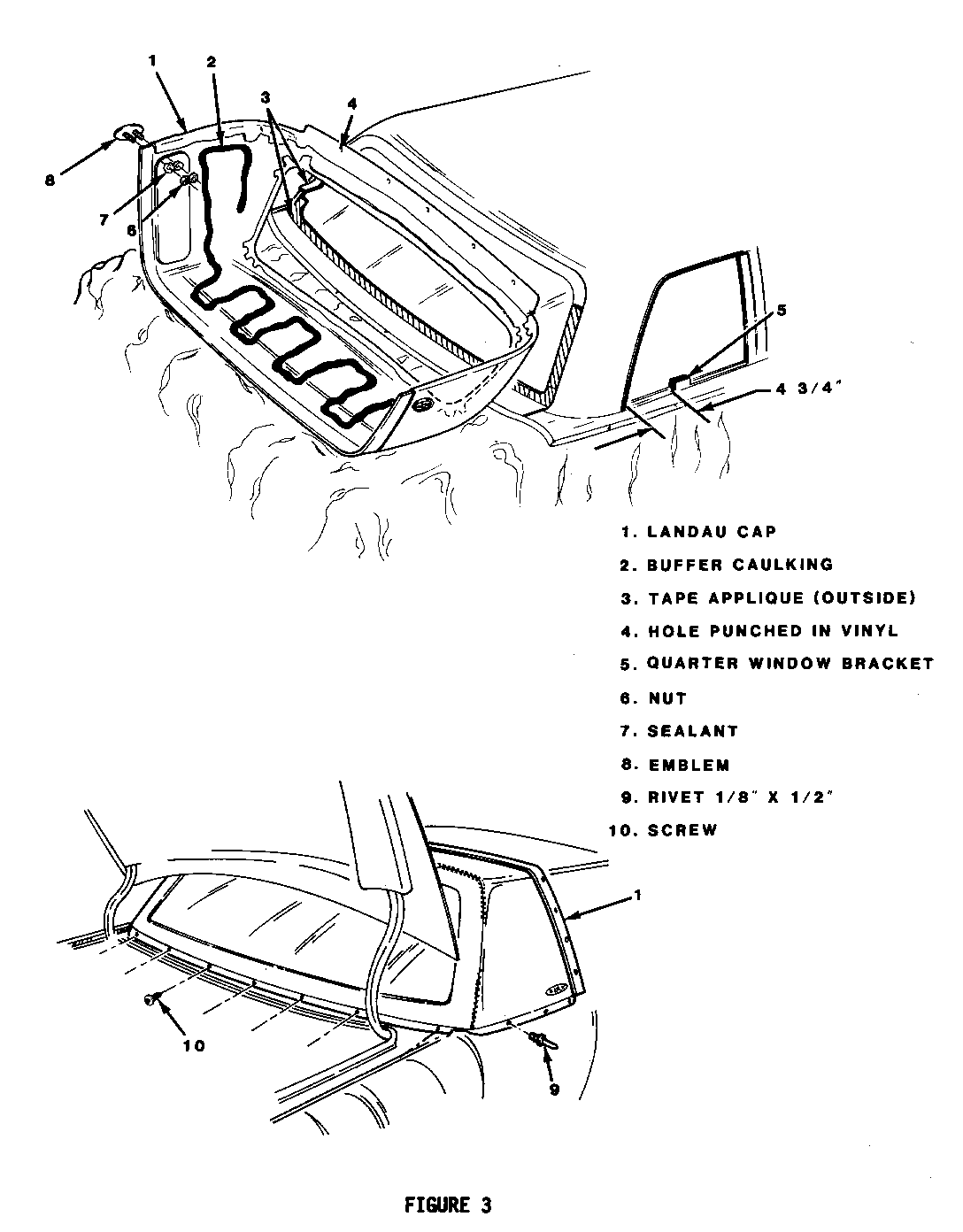
7. With deck lid open, seven (7) screws holding landau cap assembly to vehicle's body under backlight glass in trunk opening (Figure 3).
8. Cap assembly, with assistance of helper, along with roof band brackets, roof substrate, and quarter window filler panels. Work cap free of roof and buffer caulking (Figures 2 and 3).
NOTICE: The following step applies only if new quarter window glass is to be installed and inner panel must be removed.
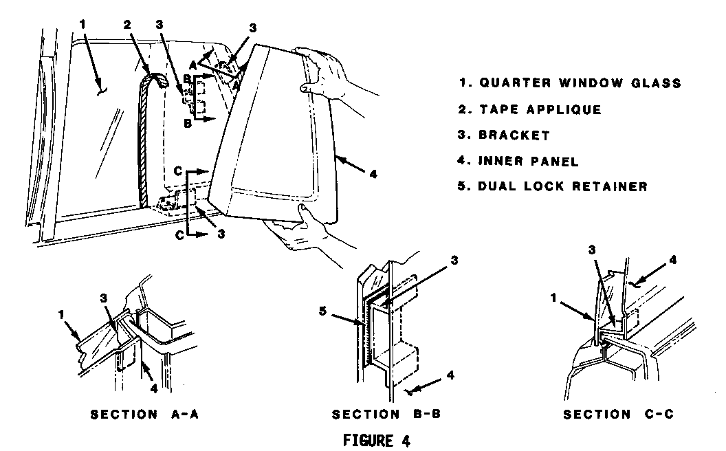
9. Inner panels by pulling panel's forward edge loose from glass and working brackets from bottom sill and under panel behind glass area (Figure 4).
Clean:
----- Roof panel, backlight glass, and belt line areas.
NOTICE: It is not necessary to completely remove old caulking, however, all high spots must be eliminated.
Install or Connect
Tools Required:
Pry type tool such as nylon or fiber stick.
NOTICE: If existing cap assembly is to be reinstalled, use existing rivet holes. However, new holes should be drilled for a new top as this will give a better fit to vehicle. Therefore, before a new cap is installed, fill all existing holes not to be used with butyl sealant. All new holes drilled in metal roof panel must be coated with zinc chromate.
1. Blackout applique tape on any backlight and quarter window glass that has been replaced. Using the landau cap assembly as a guide, mark new glass with grease pencil and apply tape as shown in Figures 2 and 3. Tape to be on outside of backlight glass and on inside of quarter window glass.
2. Quarter window to cap assembly bracket. This bracket must be installed as shown in Figure 2 only if quarter window is new.
NOTICE: Punch holes through vinyl at seven (7) plates in new cap assembly where screws will attach cap assembly to vehicle at rear.
Also, if Riviera logo emblems are not on new cap assembly when received, punch two (2) holes in vinyl, through holes in fiberglas behind quarter window, so emblems can be installed.
3. Riviera logo emblems, if needed, by first covering emblem studs with sealant, and then securing with nuts to cap assembly (Figure 2). Check to be sure "R" on emblem will be right side up when cap assembly is installed.
4. With assistance of helper, place landau cap assembly on vehicle's roof. Position by aligning existing holes in lower rear section of landau cap to holes in trunk opening. Push down and forward (Figure 3).
5. Landau cap assembly in rear trunk opening with seven (7) self tapping screws (Figure 3).
6. Position roof substrate under cap assembly's forward edge across top of roof. Also, quarter window fillers under cap's forward edges on each side. Trim roof substrate if necessary (Figure 2).
NOTICE: Roof band brackets will determine how far the forward edge of substrate is to be installed in front of for-ward edge of cap assembly. See Figure 2 to see that the widest edge of the roof band bracket is to be on the bottom and forward when installed.
Keep this distance all the way across the top. Suggest drilling first holes through cap and quarter window filler panels at very top of filler panels. Then, hold cap and filler panels in place with scratch awls or metal screws while drilling remaining holes.
7. Use marks made on masking tape when removing cap assembly to determine where to drill new holes. Keep a consistent space between forward cap edge and forward edges of substrate, and quarter window filler panels (see above). While holding in place, drill 1/8 in. holes, using drill stop method to prevent drill bit from going more than 112 in. deep. Holes to be next to, but not touching original holes, through cap assembly edge, substrate and quarter window filler panels. Belt line holes should be through chrome quarter side molding (Figures 2 and 3).
8. Remove and retain seven (7) screws from lower rear of cap assembly (Figure 3).
9. Remove cap assembly, roof substrate, and quarter window filler panels from roof and place cap assembly upside down on protected closed deck lid (Figure 3).
10. Blow off all metal chips from drilled areas. Apply zinc chromate to all newly drilled holes.
11. Buffer sealant caulking to underside of landau cap assembly in pattern as shown in Figure 3.
12. Landau cap assembly by positioning in place and securing lower edge of cap assembly in trunk opening with seven (7) self tapping screws (Figure 3).
13. Quarter filler panels to cap assembly using 1/8 in. x 1/2 in. aluminum rivets (Figure 2).
14. Cap assembly, along with roof substrate, and quarter window filler panels using 1/8 in. x 3/4 in. aluminum rivets (Figure 2). Use a drill stop to prevent drill bit from going more than 3/4 in. deep.
15. Belt line of cap assembly through chrome strip on vehicle using 1/8 in. x 1/2 in. aluminum rivets. Use a drill stop to prevent drill bit from going more than 1/2 in. deep (Figure 3).
NOTICE: Clean all mounting surfaces for rear deck lid and quarter lace moldings with a wax and grease remover or body prep solvent for proper adhesions.
16. Lower quarter lace moldings. Anchor at forward edge with 1/8 in. x 3/4 in. aluminum rivets after drilling 1/8 in. hole through vinyl lace molding, cap assembly, quarter window filler panel, and quarter window bracket (Figure 1).
17. Lace molding (if it is to be replaced) across rear deck lid (Figure 1).
NOTICE: If color of new landau cap and vehicle paint are not compatible (i.e. black top on white vehicle), use blackout tape applique over forward edge of rear deck lid. Allow 3/16" of tape to lay on top of deck lid and fold the remainder under front edge as shown in Figure 1. Trim off excess tape.
18. Roof band brackets. Bracket to be approximately six (6) inches from centerline of roof with widest edge on bottom and forward. Secure with 1/8 in. x 3/4 in. aluminum rivets as shown in Figure 2. Use a drill stop to prevent drill bit from going more than 3/4 in. deep.
19. Using template of holes from old cap and 3/6 in. drill bit, drill four (4) holes through edge of cap assembly and each quarter window filler panel for roof band molding clips (Figure 1).
20. Roof band molding by sliding upper end of each side across top and over forward edge of cap assembly and front and rear edges of roof band brackets (top end of band should be bent out where shown in Figure 1 for easier installation over brackets). Use fiber stick to ensure edges of band are holding around edges of cap assembly and brackets.
21. Sides of roof band molding by aligning four (4) clips in molding with 3/6 in. holes drilled in cap assembly and pushing in (Figure 1).
NOTICE: Do not dent or bend roof band molding, push gently using only fiber stick tool to pry up cap and bracket edges.
22. Roof band moldings at top center. Drill two (2) 1/8 in. holes, insert spacers and rivet with 1/8 in. x 3/4 in. rivets (Figure 1). Use drill bit stop to prevent drill bit from going more than 3/4 in. deep.
23. Center escutcheon at top center of roof band molding using fiber stick to get edges of escutcheon under molding to secure (Figure 1).
24. Rear quarter window inner panel assemblies by first placing panels in place and marking where forward bracket will contact window glass. Separate Duel Lock halves, peal off protective cover and stick Dual Lock halves to bracket and quarter window glass (Figure 4).
25. Using fiber stick, pry up existing panels slightly, enough for brackets on rear of quarter inner panel to slip under, and install rear brackets of inner panel as shown in Figure 4. Secure forward edges of inner panels onto glass by pushing together Dual Lock halves on bracket and glass.


General Motors bulletins are intended for use by professional technicians, not a "do-it-yourselfer". They are written to inform those technicians of conditions that may occur on some vehicles, or to provide information that could assist in the proper service of a vehicle. Properly trained technicians have the equipment, tools, safety instructions and know-how to do a job properly and safely. If a condition is described, do not assume that the bulletin applies to your vehicle, or that your vehicle will have that condition. See a General Motors dealer servicing your brand of General Motors vehicle for information on whether your vehicle may benefit from the information.
