Connecting Rod Bearings
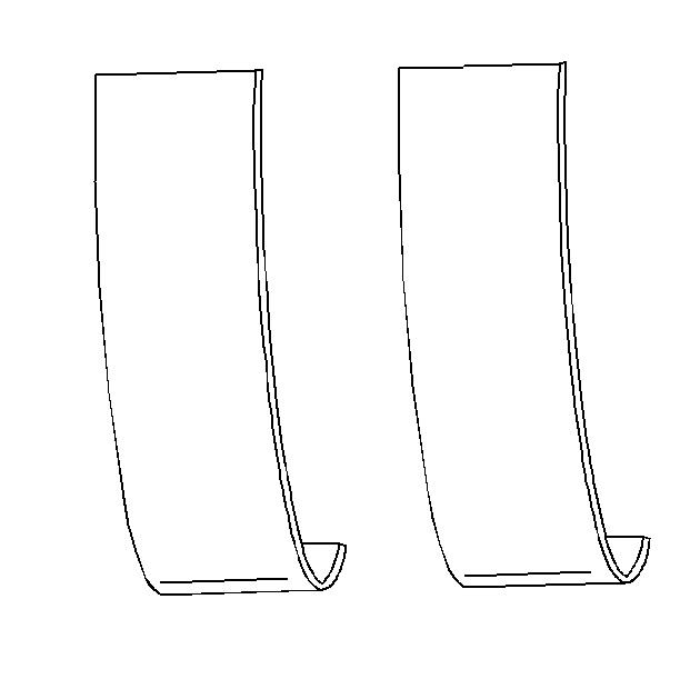
Engine bearings are the precision insert type. The bearings are available for service use in standard and 0.001 in undersize.
Notice: Do not scrape, shim, or file bearing inserts. If the bearing surface of the insert is touched with bare fingers, the skin oil and acids will etch the bearing surface.
- Inspect bearing surfaces for the following conditions:
- Inspect the outer surfaces for the following conditions:
- Inspect the thrust surfaces (main thrust bearing) for the following conditions:
- Inspect the connecting rods or main bearing bores. Complete the following steps:
- Inspect the bearing cap bolts. Replace the bolts, if the bolts are stretched.
- In order to determine if a bolt is stretched, compare it to a new bolt.

| • | Wear |
| • | Gouges |
| • | Embedded foreign material -- If foreign material is found, determine its nature and source. Inspect the oil pan sludge and residue. |
| • | Uneven side to side wear -- If uneven wear is found, check for a bent crankshaft or tapered bearing journals. |
| • | Wear -- Surface wear indicates either movement of the insert or high spots in the surrounding material (spot wear). |
| • | Overheating (discoloration) |
| • | Looseness or rotation (flattened tangs and wear grooves) |
| • | Wear |
| • | Grooving -- Grooves are caused by irregularities of the crankshaft thrust surface. Refer to Crankshaft and Bearing Removal and to Crankshaft and Bearing Installation . |
Important: Carefully investigate bearing failure, other than normal wear.
| 4.1. | Torque the bearing cap to specifications. |
| 4.2. | Measure the bore for taper and out of round. |
| 4.3. | Ensure that taper or out of round does not exist. |
Bearing Clearance
In order to determine the correct replacement insert size, measure the bearing clearance accurately. Either of the following two methods may be used: however, method A gives more reliable results and is preferred.
- Method A -- yields measurements from which the bearing clearance can be computed.
- Method B -- yields the bearing clearance directly. Method B does not give any indication of bearing or journal runout.
Method A
- Measure the crankshaft journal diameter with a micrometer in several places.
- Ensure the measurements are approximately 90° apart.
- Average the measurements.
- Measure taper and runout
- Ensure that the bearing inserts are installed in the correct bore, and torqued to specification.
- Measure the bearing insert ID with an inside micrometer.
- Measure using new inserts, if the inserts are being replaced.
- If the readings are within limits, select a suitable set of inserts.
- Bearing sets are available in standard and undersize in order to keep clearances within limits.
- If clearances cannot be brought into specifications with selectively fitting bearings, replace the crankshaft.
Method B
- Install all the bearing inserts and the crankshaft into the block.
- Place a piece of gaging plastic across the entire bearing width.
- Seat the bearing cap carefully. Tap the bearing cap lightly with a suitable tool.
- Tighten the bearing cap bolts to specification.
- Remove the bearing cap.
- Leave the gaging plastic in place. It does not matter whether the gaging plastic adheres to the journal or to the bearing cap.
- Measure the flattened gaging plastic at its widest point with the scale printed on the gaging plastic package.
- Remove all traces of the gaging plastic after measuring.
Notice: In order to prevent the possibility of cylinder block or crankshaft bearing cap damage, the crankshaft bearing caps are tapped into the cylinder block cavity using a brass, lead, or a leather mallet before the attaching bolts are installed. Do not use attaching bolts to pull the crankshaft bearing caps into the seats. Failure to use this process may damage a cylinder block or a bearing cap.
Important: Do not rotate the crankshaft.
Bearing Installation
Tools Required
J 36660-A Torque Angle Meter
Notice: Do not scrape, shim, or file bearing inserts. If the bearing surface of the insert is touched with bare fingers, the skin oil and acids will etch the bearing surface.
- Dip the bearing cap bolts in clean engine oil.
- Place inserts into the bearing cap and into the engine block or connecting rod.
- The inserts will project slightly when put into place. Ensure that the inserts project an equal distance on both sides.
- Make sure the insert tangs are engaged.
- In the case of a main bearing insert of the thrust bearing type, coat the thrust surface with GM approved lubricant or equivalent.
- Lubricate the bearing surface with clean engine oil.
- Install the crankshaft or connecting rod.
- Install the bearing cap. Tap the cap gently into place with a suitable tool.
- Install the bearing cap bolts.
- Seat the crankshaft thrust bearing by tapping the crankshaft in both directions with a wooden mallet.
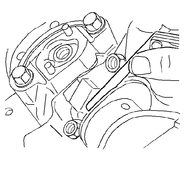
- Pry the connecting rod back and forth and check for binding. If necessary, loosen and retighten the bearing cap.
- Measure the crankshaft end play.
- Measure the connecting rod side clearance.
Important: Ensure that the bearing cap bolt holes and the cap mating surfaces are clean and dry.
Notice: Upper and lower inserts may be different. Do not obstruct any oil passages.
Notice: In order to prevent the possibility of cylinder block or crankshaft bearing cap damage, the crankshaft bearing caps are tapped into the cylinder block cavity using a brass, lead, or a leather mallet before the attaching bolts are installed. Do not use attaching bolts to pull the crankshaft bearing caps into the seats. Failure to use this process may damage a cylinder block or a bearing cap.
Tighten
Tighten the bolts to 35 N·m (26 lb ft). Use
the J 36660-A
in order to tighten the bolts
an additional 50°.

