Caution: This vehicle is equipped with Supplemental Inflatable Restraint (SIR).
Refer to the Cautions in the On-Vehicle Service and the SIR Component and
Wiring Location view in the Supplemental Inflatable (SIR) System before any
performing service on or around SIR components or wiring. Failure to follow
the Cautions could result in possible air bag deployment, personal injury,
or otherwise unneeded SIR system repairs.
Notice: Always use the correct fastener in the proper location. When you replace
a fastener, use ONLY the exact part number for that application.
The applicable service procedure will identify, where necessary, those
fasteners that must be replaced after removal; or those fasteners that require
the use of thread locking compound or thread sealant.
UNLESS OTHERWISE SPECIFIED, do not use supplemental coatings (paints,
greases, or other corrosion inhibitors) on threaded fasteners or fastener
joint interfaces. Generally, such coatings adversely affect the fastener torque
and the joint clamping force, and may damage the fastener.
When you install fasteners, use the correct tightening sequence and
specifications.
Following these instructions can help you avoid damage to parts and
systems.
The fuel supply is stored in the fuel tank. An electric
fuel pump, inside the modular fuel sender assembly (inside the fuel tank)
pumps fuel through an in-pipe filter to the fuel injection system. The fuel
pump is designed to provide fuel at a pressure above the regulated pressure
needed by the fuel injectors. A fuel pressure regulator keeps fuel available
to the fuel injectors at a regulated pressure. Unused fuel is returned to
the fuel tank by a separate pipe. For further information on the fuel injection
system, refer to
Fuel Metering System Components
.
Unleaded fuel must be used with all gasoline engines for proper emission
control system operation. Using unleaded fuel will also decrease spark plug
fouling and extend engine oil life. Leaded fuel can damage the emission control
system, and its use can result in loss of emission warranty coverage.
All vehicles with gasoline engines are equipped with an evaporative
emission system that minimizes the escape of fuel vapors to the atmosphere.
For information regarding this system, refer to
Evaporative Emission Control System
.
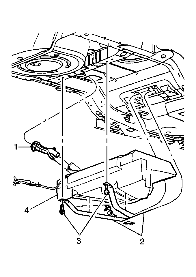
The fuel tank is used to store fuel for the vehicle. The
tank is located in the rear of the vehicle and is held in place by two metal
straps that are attached to the underbody. The fuel tank is made of plastic.
The fuel tank is not repairable. The fuel tank shape includes a reservoir
in order to maintain a constant supply of fuel around the fuel pump strainer
during low fuel conditions and aggressive vehicle maneuvers.
Fuel Tank Filler Pipe

In order to prevent refueling with leaded fuel, the fuel tank filler pipe
(1) has a built-in restrictor and deflector.
The opening in the restrictor will accept only the smaller unleaded
gasoline fuel nozzle which must be fully inserted to bypass the deflector.
The filler pipe is attached to the tank by a section of hose and two hose
clamps.
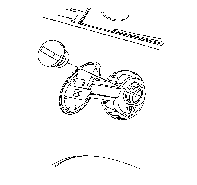
Fuel Tank Filler Pipe Cap

The fuel tank filler pipe is equipped with a threaded-type fuel tank filler
pipe cap. The threaded part of the fuel tank filler pipe cap requires several
turns counterclockwise before it can be removed. A built-in torque-limiting
device prevents over tightening of the fuel tank filler pipe cap. In order
to install the fuel tank filler pipe cap, turn the fuel tank filler pipe
cap clockwise until at least 3 clicking noises are heard. The clicking noises
signal that the correct torque has been reached and that the fuel tank filler
pipe cap is fully seated.
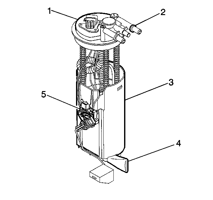
Modular Fuel Sender Assembly

The modular fuel sender assembly is attached to the top of the fuel tank,
and extends from the top of the fuel tank to the bottom.
The modular fuel sender assembly consists of the following major components:
a Fuel Sender Cover Assembly (1), Fuel Pipes (Above Cover) (2), a Fuel Pump
(3), a Fuel Pump Strainer, a Fuel pump Reservoir, a Fuel Sender Strainer (4),
a filter to reduce radio frequency interference on supercharged models, and
a ceramic card Fuel Level Sensor Assembly (5).
The fuel level sender assembly consists of the float, the wire float
arm, and the rheostat. The fuel level is sensed by the position of the float
and float arm, which operate the 90 ohm rheostat. As the float position changes,
the amount of current passing through the rheostat varies, thus changing
the guage reading on the instrument panel.
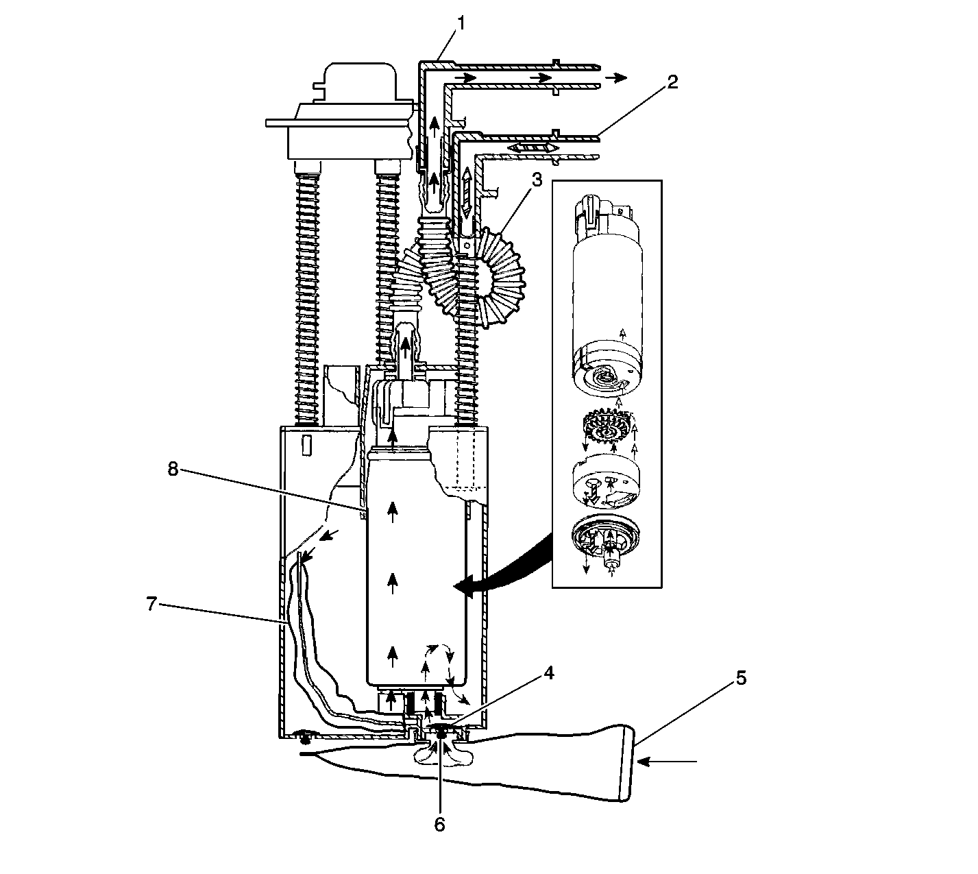
Modular Fuel Sender Fuel Flow


