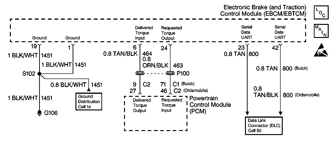
Circuit Description
The PCM provides the EBTCM with information on engine torque output via a high speed, pulse width modulated (PWM) signal on CKT 464.
The information enables the EBTCM to determine if engine torque management is required during a traction control event.
Conditions for Setting the DTC
The DTC Caw will set if the EBTCM determines that there is a signal/circuit malfunction in CKT 464.
Action Taken When the DTC Sets
The following actions are taken when the DTC sets:
| • | A malfunction DTC is stored. |
| • | The TCS is disabled. |
| • | The TRACTION OFF indicator lamp is turned ON. |
Conditions for Clearing the DTC
The DTC will clear under following conditions:
| • | Conditions for the malfunction are no longer present. Use the scan tool clear DTCs function. |
| • | 100 ignition switch key cycles have passed without detecting any malfunctions. |
Diagnostic Aids
Perform a thorough inspection of the wiring and the connectors.
Failure to carefully inspect wiring may result in a misdiagnosis. A misdiagnosis may result in replacing parts without repairing the malfunction.
Thoroughly inspect the following grounds:
| • | G101 |
| • | G102 |
| • | G106 |
| • | G110 |
The following condition can cause DTC C1277 set:
| • | An open in CKT 464 |
| • | A short to ground in CKT 464 |
| • | A short to voltage in CKT 464 |
| • | Damaged wiring or connections |
| • | Poor terminal contact |
If no circuit problem caused the DTC, perform a road test and monitor CKT 464 at the PCM when the DTC sets.
Step | Action | Value(s) | Yes | No |
|---|---|---|---|---|
1 | Was the ABS Diagnostic System Check performed? | -- | Go to Step 2 | Go to Diagnostic System Check |
2 |
Is the voltage within the specified range? | Battery Voltage | Go to Step 3 | Go to Step 4 |
3 |
Is the voltage within the specified range? | 0.75-2.5 V | Go to Step 12 | Go to Step 8 |
4 |
Is the resistance less than the specified value? | OL (Infinite) | Go to Step 5 | Go to Step 6 |
5 | Repair the short to ground in CKT 464. Refer to Wiring Repairs in Wiring Systems. Is the repair complete? | -- | Go to Diagnostic System Check | -- |
6 |
Is the resistance less than the specified value? | 2 ohms | Go to Step 13 | Go to Step 7 |
7 | Repair the open or high resistance in CKT 464. Refer to Wiring Repairs in Wiring Systems. Is the repair complete? | -- | Go to Diagnostic System Check | -- |
8 | Use the J 39200 in order to measure the voltage from the PCM connector C1 terminal 9 (Buick) or connector C2 terminal 27 (Oldsmobile) to ground. Is the voltage greater than the specified value? | 0.75 V | Go to Step 10 | Go to Step 9 |
9 | Repair the short to ground in CKT 464. Refer to Wiring Repairs in Wiring Systems. Is the repair complete? | -- | Go to Diagnostic System Check | -- |
10 | Inspect the PCM connector for poor terminal contact or damage. Did you find and correct the concern? | -- | Go to Diagnostic System Check | Go to Step 11 |
11 | Replace the PCM. Refer to Powertrain Control Module Replacement/Programming in Engine Controls - 4.0. Is the repair complete? | -- | Go to Diagnostic System Check | -- |
12 | Is the DTC set as current? | -- | Go to Step 13 | Go to Diagnostic Aids |
13 | Replace the EBTCM. Refer to Electronic Brake and Traction Control Module Replacement Is the repair complete? | -- | Go to Diagnostic System Check | -- |
