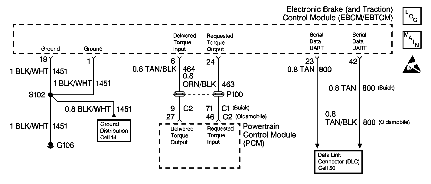
Circuit Description
When the EBTCM detects excessive wheel spin, the EBTCM will request that the PCM reduce engine torque via a high speed pulse width modulated (PWM) signal on CKT 463.
Conditions for Setting the DTC
The DTC C1278 sets when the EBTCM receives a communication failure data message from the PCM.
The DTC C1278 sets under the two following conditions:
| • | EBTCM to PCM communications. CKT 463 or CKT 800 is open or shorted |
| • | PCM driveability conditions that would set PCM DTCs. If PCM DTCs are present, the malfunction may not exist with the ABS/TCS system. Refer to Powertrain On Board Diagnostic (OBD) System Check in Engine Controls - 4.0L. |
Action Taken When the DTC Sets
The following actions are taken when the DTC sets:
| • | A malfunction DTC is stored |
| • | The TCS is disabled |
| • | The TRACTION OFF indicator lamp is turned ON |
Conditions for Clearing the DTC
The DTC will be cleared under following conditions:
| • | Conditions for the malfunction are no longer present. Use the scan tool clear DTCs function. |
| • | 100 ignition switch key cycles have passed with no malfunctions detected |
Diagnostic Aids
Perform a thorough inspection of the wiring and the connectors.
Failure to carefully inspect wiring may result in misdiagnosis. A misdiagnosis may result in part replacement with reappearance of the malfunction.
Thoroughly inspect the following grounds:
| • | G101 |
| • | G102 |
| • | G106 |
| • | G110 |
Step | Action | Value(s) | Yes | No | ||||||||||||||
|---|---|---|---|---|---|---|---|---|---|---|---|---|---|---|---|---|---|---|
1 | Was the ABS Diagnostic System Check performed? | -- | Go to Step 2 | |||||||||||||||
2 | Use the scan tool to check for PCM DTC P1571 or any other PCM DTCs. Are there any PCM DTCs? | -- | Go to Powertrain On Board Diagnostic (OBD) System Check in Engine Controls - 4.0L | Go to Step 3 | ||||||||||||||
3 |
Is the resistance less than the specified value? | 2 ohms | Go to Step 4 | Go to Step 10 | ||||||||||||||
4 |
Is the voltage within the specified range? | 4.5-5.5 V | Go to Step 5 | Go to Step 6 | ||||||||||||||
5 |
Is the voltage less than the specified value? | 1 V | Go to Step 14 | Go to Step 11 | ||||||||||||||
6 |
Is the resistance less than the specified value? | OL (Infinite) | Go to Step 12 | Go to Step 7 | ||||||||||||||
7 | Use the J 39200 in order to measure the resistance between the J 38716 pinout box terminal 24 and the PCM harness connector C1 terminal 14 (Buick) or connector C2 terminal 46 (Oldsmobile). Is the resistance less the specified value? | 2 ohms | Go to Step 8 | Go to Step 13 | ||||||||||||||
8 | Inspect the following components:
Inspect the above components for the following conditions:
Are there signs of poor terminal contact, corrosion, or damage in any of the components? | -- | Go to Step 9 | Go to Step 14 | ||||||||||||||
9 | Repair or replace any terminals, connectors and/or wiring that exhibit signs of poor terminal contact, corrosion, or damaged terminals. Refer to Wiring Repairs in Wiring Systems. Is the repair complete? | -- | -- | |||||||||||||||
10 | Repair the open or high resistance in CKT 1451. Refer to Wiring Repairs in Wiring Systems. Is the repair complete? | -- | -- | |||||||||||||||
11 | Repair the short to the voltage in CKT 463. Refer to Wiring Repairs in Wiring Systems. Is the repair complete? | -- | -- | |||||||||||||||
12 | Repair the short to ground in CKT 463. Is the repair complete? | -- | -- | |||||||||||||||
13 | Repair the open or high resistance in CKT 463. Refer to Wiring Repairs in Wiring Systems. Is the repair complete? | -- | -- | |||||||||||||||
14 | Replace the EBTCM. Refer to Electronic Brake and Traction Control Module Replacement . Is the repair complete? | -- | -- |
