SERVICE MANUAL UPDATE - SEC. 7 TRANS. UNIT REPAIR INFORMATION

SUBJECT: SERVICE MANUAL UPDATE - SECTION 7 - TRANSMISSION UNIT REPAIR INFORMATION
MODELS AFFECTED: 1992 ROADMASTER
BULLETIN COVERS:
New Product Information for 1992 HYDRA-MATIC 4L60 transmissions. This information has been updated since publication of the 1992 Service Manual and should be noted accordingly. Be certain to familiarize yourself with these updates to properly repair the 1992 HYDRA-MATIC 4L60 transmission.
DATE OF PRODUCTION CHANGE:
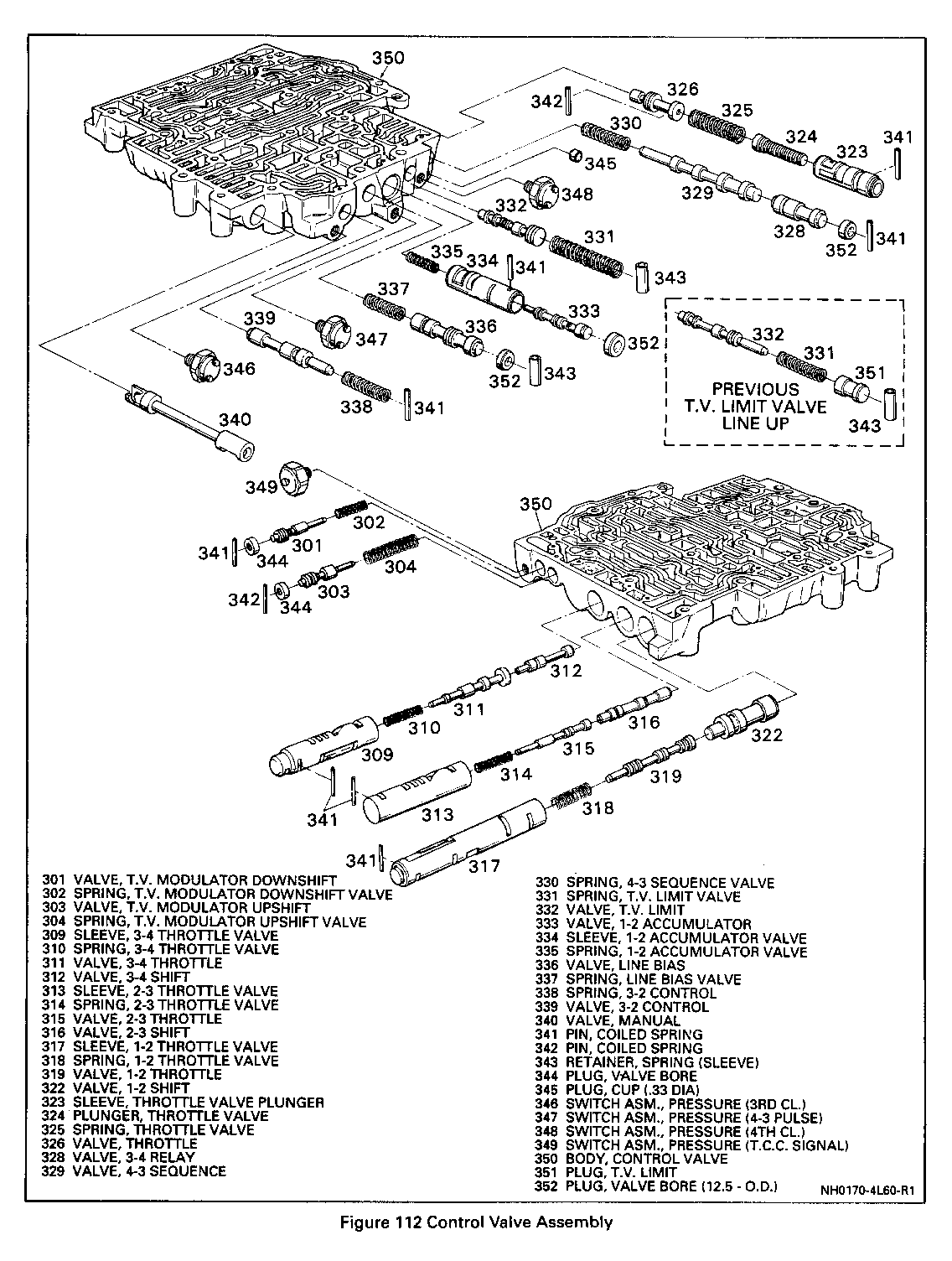
On August 14, 1991 (Julian Date 226), the HYDRA-MATIC 4L60 transmissions were built with a new calibration that changed the TV limit line-up. The changes included a new TV limit valve (Ill. 332), a new TV limit valve spring (Ill. 331), and eliminates the TV limit plug (Ill. 351). Also included is an updated line pressure check chart and an updated 2nd apply piston and housing application chart.
SERVICE MANUAL REFERENCE:
Update your 1992 Service Manual Section 7 Transmission with the following three (3) pages.
LINE PRESSURE CHECK PROCEDURE
* CHECK TRANSMISSION FLUID LEVEL * CHECK AND ADJUST TV CABLE * CHECK OUTSIDE MANUAL LINKAGE AND CORRECT * CHECK ENGINE TUNE * INSTALL PRESSURE GAGE * CONNECT TACHOMETER TO ENGINE * CHECK PRESSURE AS FOLLOWS:
Minimum TV Line Pressure Check
Set the TV cable to specification; and with the brakes applied, take the line pressure readings in the ranges and at the engine rpm indicated in the chart below.
Full TV Line Pressure Check
Full TV line pressure readings are obtained by tying or holding the TV cable to the full extent of its travel; and with the brakes applied, take the line pressure readings in the ranges and at the engine rpm indicated in the chart below.
*NOTICE: Total running time combination not to exceed 2 minutes.
CAUTION:
Brakes must be applied at all times.
1992 HYDRA-MATIC 4L60 TRANSMISSION PRESSURES
NORMAL PRESSURE NORMAL PRESSURE RANGE MODEL AT MINIMUM TV AT FULL TV ----- ----- --------------- --------------- kPa PSI kPa PSI --- --- --- --- PARK, AAM 518-587 75-85 866-1063 126-154 NEUTRAL, ACM 451-515 66-75 823-1020 119-148 OVERDRIVE & ADM,AKM,APM 518-587 75-85 1097-1381 159-200 BCM 451-515 65-75 864-995 125-147 BFM,BJM,FUM,YDM 451-515 65-75 1116-1430 1162-208 MANUAL 3RD BHM,BWM,CAM,CBM,KAM, 451-515 65-75 851-1063 123-154 KMM,MJM,MNM,WAM @ 1000 RPM CCM,CFM,KHM,KLM,TMM,WBM 451-515 85-75 947-1185 137-172 CHM,CJM,KJM,RAM,TNM,WCM 451-515 65-75 914-1149 133-167 DDM 518-587 75-85 981-1221 142-177 FBM 451-515 65-75 918-1146 133-166 FTM,FZM 451-515 65-75 1073-1354 155-196 FUM 518-587 75-85 1350-1732 195-251 LAM,LBM,LCM,LDM,LFM 451-515 65-75 871-1091 126-158 LHM 518-587 75-85 1332-1766 193-256 MMM,MSM 518-587 75-85 935-1173 135-170 SAM,SFM 451-515 65-75 845-1068 123-155 SHM,SPM,TLM 451-515 65-75 969-1231 141-179 TAM,TBM 451-515 65-75 914-1188 132-172 TWM 451-515 65-75 1002-1267 145-183
REVERSE AAM 738-836 107-121 1234-1515 197-220 @ 1000 RPM ACM,BCM,DAM 742-847 108-123 1354-1677 197-244 ADM,AKM,APM 738-836 107-121 1563-1967 226-285 BFM,BJM,YDM 742-847 108-123 1834-2351 266-341 BHM,BWM,CAM,CBM,DBM,KAM,KMM,MJM,MNM,WAM 742-847 108-123 1400-1747 203-253 CCM,CFM,KHM,KLM,TMM,WBM 742-847 108-123 1556-1948 226-283 CHM,CJM,KJM,RAM,TNM,WCM 742-847 108-123 1503-1889 218-274 DDM 738-836 108-123 1397-1739 202-252 FBM 580-662 84-96 1180-1472 171-214 FTM,FZM 742-847 108-123 1763-2225 256-323 FUM 665-754 97-109 1734-2225 251-322 LAM,LBM,LCM,LDM,LFM 741-845 107-123 1429-1790 207-260 LHM 665-754 97-109 1710-2268 248-329 MMM,MSM 738-836 108-123 1331-1671 193-242 SAM,SFM 580-662 84-96 1085-1372 157-199 SHM,SPM,TLM 742-847 108-123 1593-2023 231-293 TAM,TBM 741-845 107-123 1503-1952 218-283 TWM 741-845 107-123 1646-2082 238-301
MANUAL 2ND AAM,ADM,AKM,APM,BBM,DDM, 1121-1269 163-184 1121-1269 163-180 MMM,MSM & MANUAL LO ACM,BCM,BHM,BWM,CAM,CBM,CCM, 1127-1286 163-186 1127-1286 163-186 CFM,CHM,CJM,DAM,DBM @ 1000 RPM FBM,FTM,FZM,KAM,KJM,KMM,MJM, MNM,RAM,SAM,SFM,SHM SPM,TAM,TBM,TLM,TMM,TNM,WAM,WBM,WCM,YDM LAM,LBM,LCM,LDM,LFM 1191-1359 173-197 1191-1359 173-197 FUM,LHM 1293-1465 188-223 1293-1465 188-213
Line pressure is basically controlled by pump output and the pressure regulator valve. In addition, line pressure is boosted in Reverse, Second and Lo by the reverse boost valve.
Also, in the Neutral, Drive, Intermediate and Reverse positions of the selector lever, the line pressure should increase with throttle opening because of the TV system. The pressure is controlled by the TV cable, the throttle lever and bracket assembly and the TV link, as well as the control valve assembly.
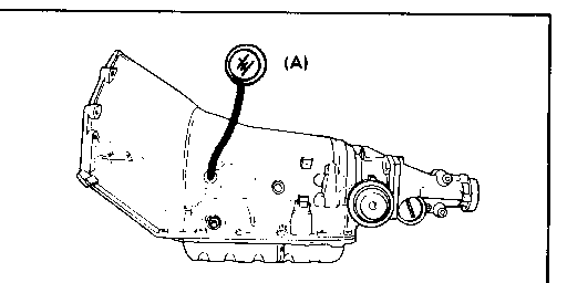
The main line pressure tap plug is located on the left side of the transmission above the outside manual lever.
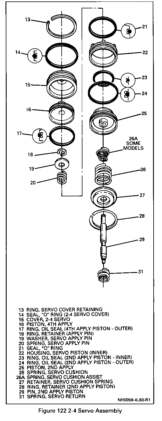
o Cover (15) for porosity or damage.
o Seals for:
- Nicks or cuts.
- Freeness in the seal groove.
o Springs for distortion.
o Pin for wear or burrs.
IMPORTANT
o Check servo bore in the case for any wear which may cut the servo seals.
MEASURE
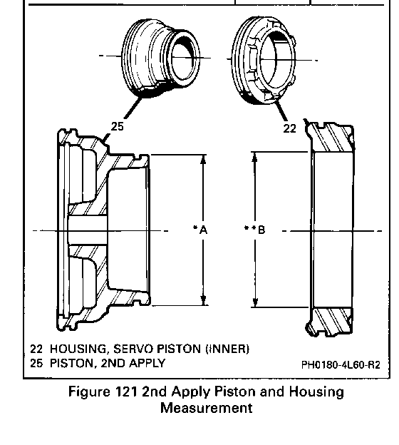
Figure 121
1. Measure piston (25) dimension *A.
2. Measure housing (22) dimension **B.
3. Check model application.
2ND APPLY PISTON AND HOUSING APPLICATION
PISTON HOUSING MODEL DIMENSION DIMENSION ----- *A **B --------- ---------- YAM, YCM, YDM, LHM 44.64mm 45.54mm (1.78") (1.79")
AAM,ADM,ALM,ACM,BBM,BCM, BHM, BFM, BRM, BWM, CJM, CHM, 57.85mm 58.74mm DDM, FUM, FZM, HJM, KJM, LBM, (2.28") (2.3l") LCM, LDM, LFM, TAM, TBM, WCM
CAM, CBM, CCM, CFM, BAM, FBM, FTM, HBM, HLM, HDM, KHM, KMM, 63.10mm 64.00mm MDM, MJM, MMM, MNM, MSM, SAM, (2.48") (2.52") SFM, SHM, TLM, TWM, WAM, WBM


General Motors bulletins are intended for use by professional technicians, not a "do-it-yourselfer". They are written to inform those technicians of conditions that may occur on some vehicles, or to provide information that could assist in the proper service of a vehicle. Properly trained technicians have the equipment, tools, safety instructions and know-how to do a job properly and safely. If a condition is described, do not assume that the bulletin applies to your vehicle, or that your vehicle will have that condition. See a General Motors dealer servicing your brand of General Motors vehicle for information on whether your vehicle may benefit from the information.
