SERVICE MANUAL UPDATE-SEC. 5E1 ABS-INDICATOR ON W/NO DTC SET

SUBJECT: 5El ANTILOCK BRAKE SYSTEM "ANTILOCK" INDICATOR "ON" WITH NO DTC(S) SET REVISED CHART A VEHICLES AFFECTED: 1991-93 "B" MODEL
This bulletin updates the 1991, 1992 and 1993 B-Car Service Manuals, Section 5E1. Please replace the Chart A diagnostic flow charts and facing pages found in the 1991, 1992 and 1993 B-Car Service Manuals with the aftached pages.
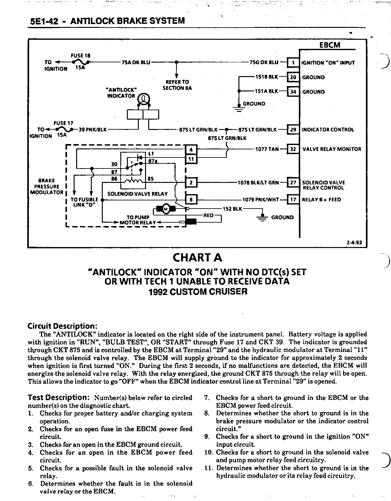
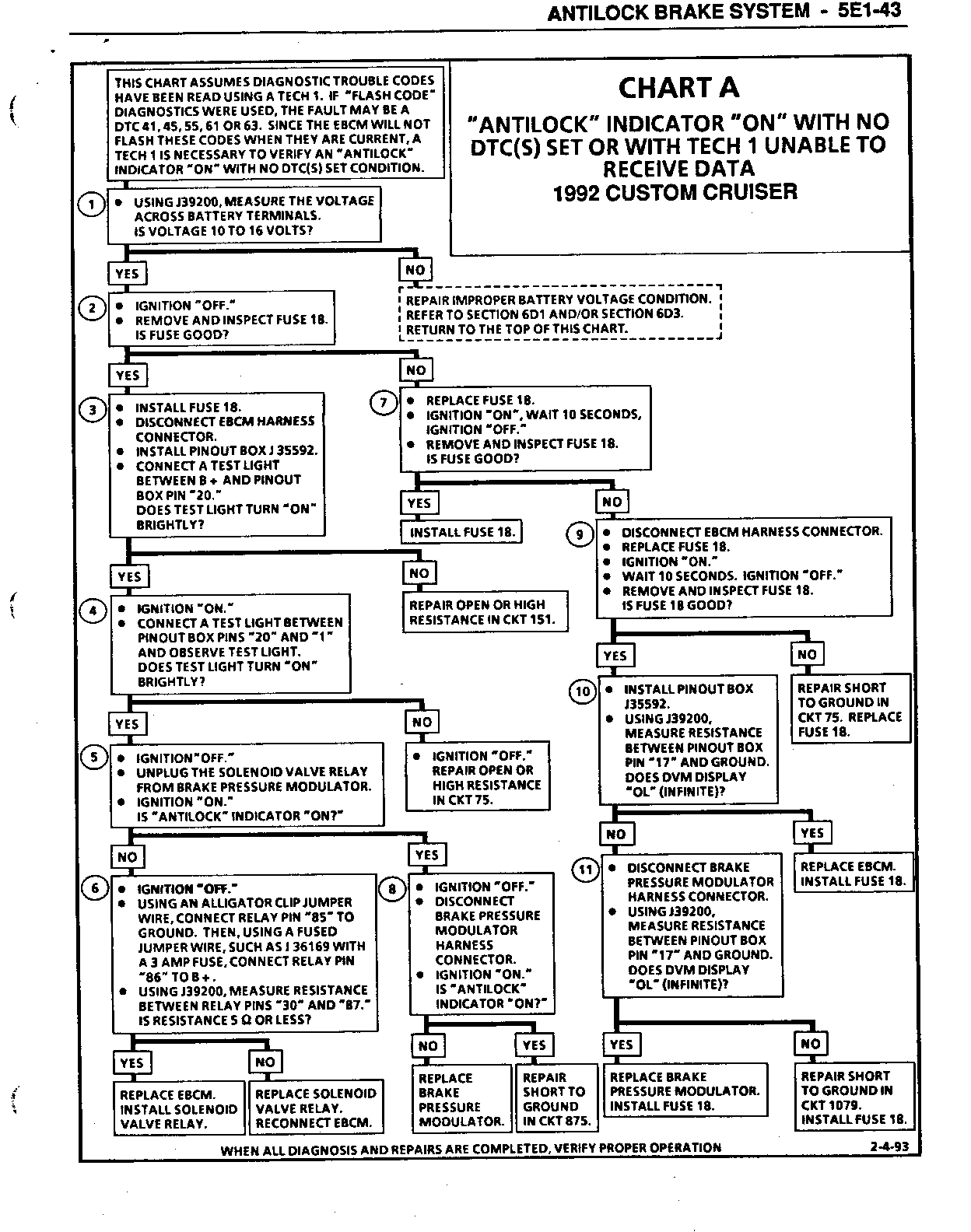
CHART A "ANTILOCK- INDICATOR -ON- WITH NO DTC(S) SET OR WITH TECH 1 UNABLE TO RECEIVE DATA ALL 1992 CHEVROLET AND OLDSMOBILE 1992 BUICK AFTER VIN NR421428 ALL 1993 CH EVROLET AND BUICK
Circuit Description:
The "ANTILOCK" indicator is located on the right side of the instrument panel. Battery voltage is applied with ignition in "RUN", "BULB TEST", OR "START" through Fuse 17 and CKT 39. The indicator is grounded through CKT 875 and is controlled by the EBCM at Terminal "29" and the hydraulic modulator at Terminal "ll" through the solenoid valve relay. The EBCM will supply ground to the indicator for approximately 2 seconds when ignition is first turned "ON." During the first 2 seconds, if no malfunctions are detected, the EBCM will energize the solenoid valve relay. With the relay energized, the ground CKT 875 through the relay will be open. This allows the indicator to go "OFF" when the EBCM indicator control line at Terminal "29" is opened.
Test Description: Number(s) below refer to circled number(s) on the diagnostic chart.
1. Checks for proper battery and/or charging system operation.
2. Checks for an open fuse in the EBCM power feed circuit.
3. Checks for an open in the EBCM ground circuit.
4. Checks for an open in the EBCM power feed circuit.
5. Checks for a possible fault in the solenoid valve relay.
6. Determines whether the fault is in the solenoid valve relay or the EBCM.
7. Checks for a short to ground in the EBCM or the EBCM power feed circuit.
8. Determines whether the short to ground is in the brake pressure modulator or the indicator control circuit."
9. Checks for a short to ground in the ignition "ON" input circuit.
10. Checks for a short to ground in the solenoid valve and pump motor relay feed circuitry.
11. Determines whether the short to ground is in the hydraulic modulator or its relay feed circuitry.
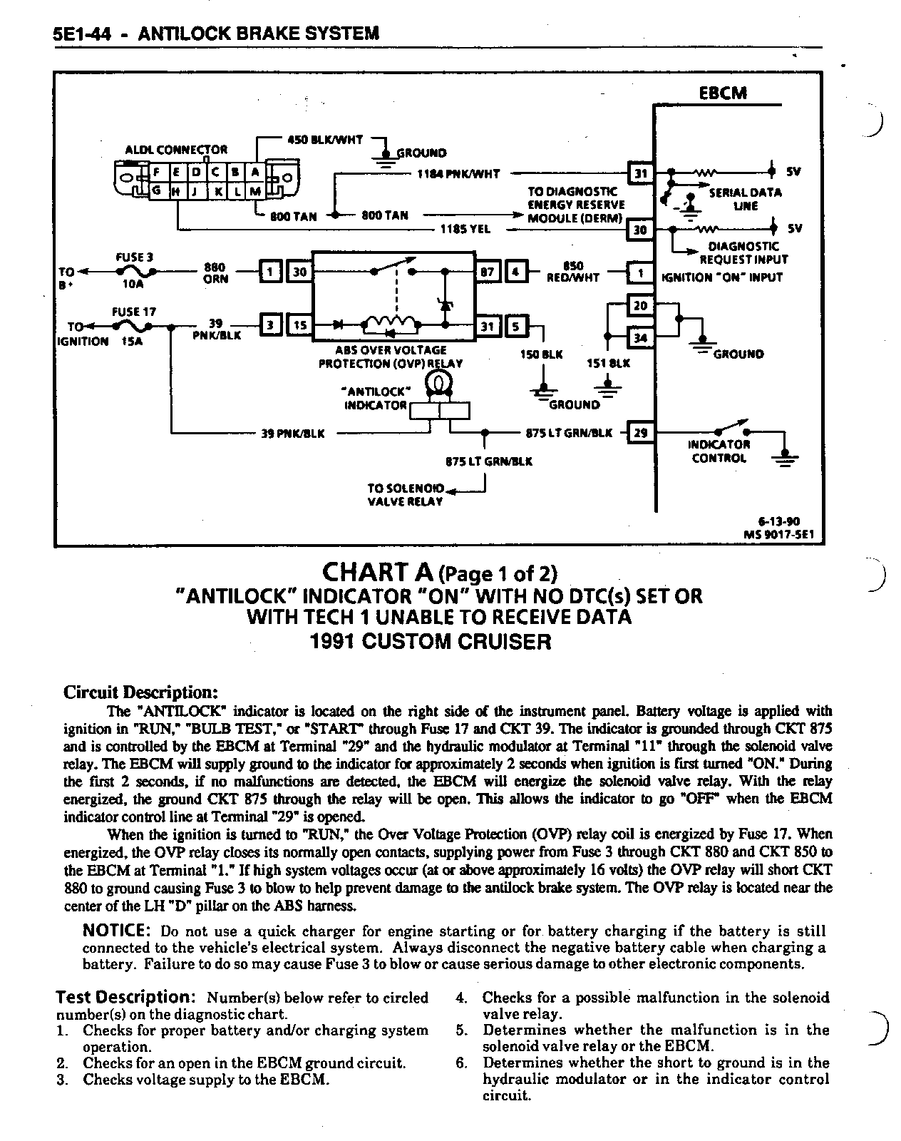
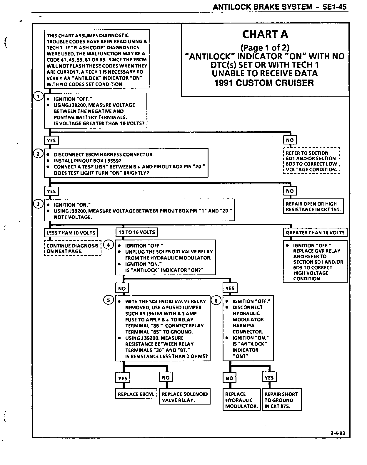
CHART A (Page 1 of 2) "ANTILOCK" INDICATOR "ON" WITH NO DTC(S) SET OR WITH TECH 1 UNABLE TO RECEIVE DATA ALL 1991 CHEVROLET AND OLDSMOBILE 1992 BUICK BEFORE VIN NR421429
Circuit Description:
The "ANTILOCK" indicator is located on the right side of the instrument panel. Batterv voltage is applied with ignition in "RUN", "BULB TEST", or "START" through Fuse 17 and CKT 39. The indicator is grounded through CKT 875 and is controlled by the EBCM at Terminal "29" and the hydraulic modulator at Terminal "11" through the solenoid valve relay. The EBCM will supply ground to the indicator for approximately 2 seconds when ignition is first turned "ON." During the first 2 seconds, if no malfunctions are detected, the EBCM will energize the solenoid valve relay. With the relay energized, the ground CKT-875 through the relay will be open. This allows the indicator to go "OFF" when the EBCM indicator control line at Terminal "29" is opened.
When the ignition is turned to "Run," the Over Voltage Protection (OVP) relay coil is energized by Fuse 17 (Fuse 18, Buick). When energized, the OVP relay closes its normally open contacts, supplying power from Fuse 3 through CKT 880 and CKT 850 to the EBCM at Terminal "1". If high system voltages occur (at or above approximately 16 volts) the OVP relay will short CKT 880 to ground causing Fuse 3 to blow to help prevent damage to the antilock brake system. The OVP relay is located inside the luggage compartment above the LH wheelhouse.
NOTICE: Do not use a quick charger for engine starting or for battery charging if the battery is still connected to the vehicle's electrical system. Always disconnect the negative battery cable when charging a battery. Failure to do so may cause Fuse 3 to blow or cause serious damage to other electronic components.
Test Description: Number(s) below refer to circled number(s) on the diagnostic chart.
1. Checks for proper battery and/or charging system operation.
2. Checks for an open in the EBCM ground circuit.
3. Checks voltage supply to the EBCM.
4. Checks for a possible malfunction in the solenoid valve relay.
5. Determines whether the malfunction is in the solenoid valve relay or the EBCM.
6. Determines whether the short to ground is in the hydraulic modulator or in the indicator control circuit.
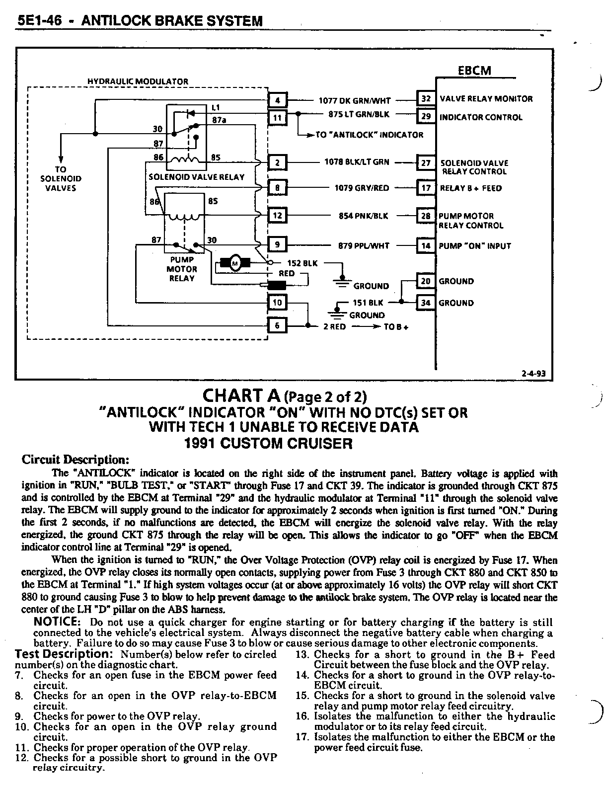
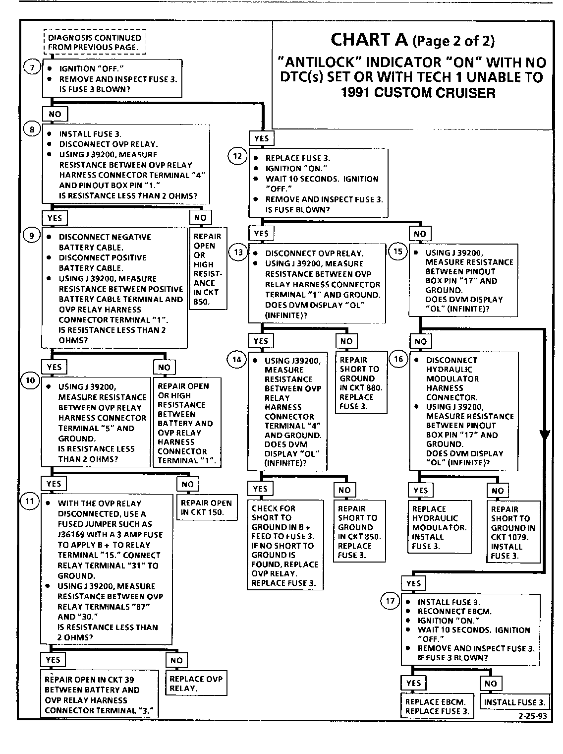
CHART A (Page 2 of 2) "ANTILOCK" INDICATOR "ON" WITH NO DTC(S) SET OR WITH TECH 1 UNABLE TO RECEIVE DATA ALL 1991 CH EVROLET AND OLDSMOBILE 1992 BUICK BEFORE VIN NR421429
Circuit Description:
The "ANTILOCK" indicator is located on the right side of the instrument panel. Battery voltage is applied with ignition in "RUN". "BULB TEST", OR "START" through Fuse 17 and CKT 39. The indicator is grounded through CKT 875 and is controlled by the EBCM at Terminal "29" and the hydraulic modulator at Terminal "ll" through the solenoid valve relay. The EBCM will supply ground to the indicator for approximately 2 seconds when ignition is first turned "ON." During the first 2 seconds, if no malfunctions are detected, the EBCM will energize the solenoid valve relay. With the relay energized, the ground CKT 875 through the relay will be open. This allows the indicator to go "OFF" when the EBCM indicator control line at Terminal "29" is opened.
When the ignition is turned to "Run," the Over Voltage Protection (OVP) relay coil is energized by Fuse 17 (Fuse 18, Buick). When energized, the OVP rela closes its normally open contacts supplying power from Fuse 3 through CKT 880 and CKT 850 to the EBCM at Terminal "1". if high system voltages occur (at or above approximately 16 volts) the OVP relay will short CKT 880 to ground causing Fuse 3 to blow, to help prevent damage to the antilock brake system. The OVP relay is located inside the luggage compartment above the LH wheelhouse.
NOTICE: Do not use a quick charger for engine starting or for battery charging if the battery is still connected to the vehicle's electrical system. Always disconnect the negative battery cable when charging a battery. Failure to do so may cause Fuse 3 to blow or cause serious damage to other electronic components.
Test Description: Number(s) below refer to circled numbers on the diagnostic chart.
7. Checks for an open fuse in the EBCM power feed circuit.
8. Checks for an open in the OVP relay-to-EBCM circuit.
9. Checks for power to the OVP relay.
10. Checks for an open in the OVP relay ground circuit.
11. Checks for proper operation of the OVP relay.
12. Checks for a possible short to ground in the OVP relay circuitry.
13. Checks for a short to ground in the B + Feed Circuit between the fuse block and the OVP relay.
14. Checks for a short to ground in the OVP relay-to-EBCM circuit.
15. Checks for a short to ground in the solenoid valve relay and pump motor relay feed eircuitry.
16. Isolates the malfunction to either the hydraulic modulator or to its relay feed circuit.
17. Isolates the malfunction to either the EBCM or the power feed circuit fuse.
General Motors bulletins are intended for use by professional technicians, not a "do-it-yourselfer". They are written to inform those technicians of conditions that may occur on some vehicles, or to provide information that could assist in the proper service of a vehicle. Properly trained technicians have the equipment, tools, safety instructions and know-how to do a job properly and safely. If a condition is described, do not assume that the bulletin applies to your vehicle, or that your vehicle will have that condition. See a General Motors dealer servicing your brand of General Motors vehicle for information on whether your vehicle may benefit from the information.
