THM 125/125C TRANS.REVISIONS P/N CHANGES AND TRANS. IDENT.

VEHICLE AFFECTED: Vehicles Equipped With Late 1984 And All 1985 Model 125/125C Transmissions
Sarting in May, 1984, a new oll pump drive shaft and spacer assembly, pump shaft bearing and seal assembly and control valve and pump assembly went into production on all THM 125/125C transmissions built in the United States.
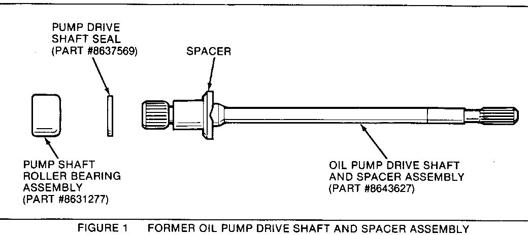
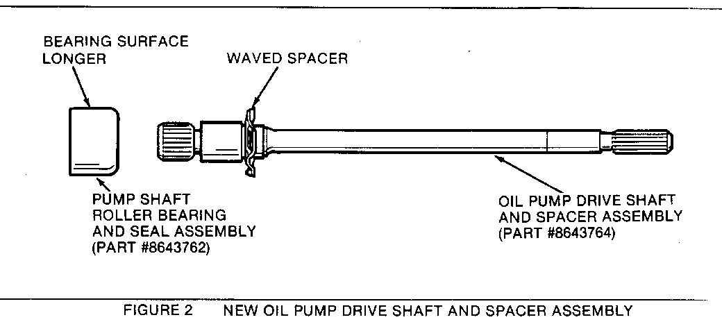
The new parts provide easier and improved assembly procedures. The former parts (Fig. 1) are not interchangeable with the new parts (Fig. 2) listed above for the following reasons.
The new oil pump drive shaft and spacer assembly has a thinner spacer and a longer bearing journal diameter to accommodate the new pump shaft bearing and seal assembly (Fig. 2).
The new pump shaft bearing and seal assembly was also made longer in length to accommodate the seal as part of the bearing assembly (Fig. 2).
The new control valve and pump assemblies were changed to accommodate the new oil pump drive shaft and roller pump shaft bearing and seal assemblies.
Refer to Chart 1 for the serial number breakpoints. If the transmission being serviced has a serial number less than the number shown in Chart 1, it will have the former parts (refer to the 1984 parts list book). If the number is the same or greater, it will have the new parts (refer to Charts 2 and 3 for new part numbers and model applications).
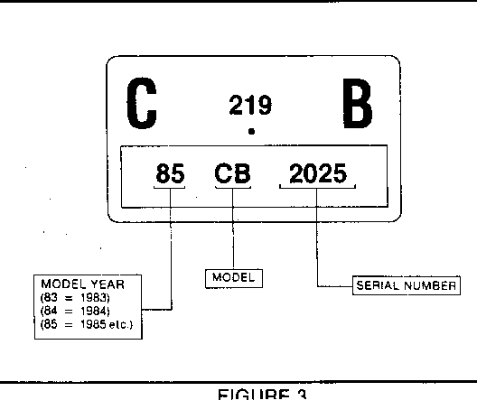
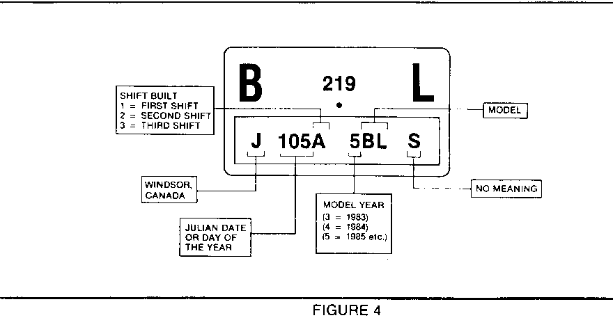
Important: All THM 125C transmissions built in Canada will have these new parts beginning start of production 1985. Some models THM 125C transmissions built in Canada are also built in the United States and can be distinguished from each other by their nameplates. The U.S. models have serial numbers (Fig. 3) and Canadian models have Julian Dates (Fig. 4).
Note: This change affects only the transmissions built in the United States.
CHART I
SERIAL NUMBERS STARTING WITH NEW OIL PUMP SHAFT AND SPACER ASSEMBLY, PUMP SHAFT BEARING AND SEAL ASSEMBLY, AND CONTROL VALVE AND PUMP ASSEMBLY.
MODEL SERIAL NO. MODEL SERIAL NO. ----- ----------- ----- ---------- CA 2921 EN 4986 CB 240974 EW 1656 CC 1887 HC 2355 CE 83327 HM 3147 CF 8695 HS 20389 CT 4840 HX 7171 EF 7651 HY 33059 EI 7493 PD 2762 EK 11230 PE 70659 EL 4824 PF 34901 EM 3343 PG 69397 EQ 14460 PI 9033 EB 3452 PW 90895 EP 2433
CHART 2
PART NAME PART NUMBER MODEL --------- ------------ ----- OIL PUMP DRIVE SHAFT AND SPACER 8643764 ALL ASSEMBLY
PUMP SHAFT BEARING AND 8643762 ALL SEAL ASSEMBLY
CHART 3
NEW CONTROL VALVE BODY ASSEMBLIES STARTING WITH SERIAL NUMBERS SHOWN IN CHART NUMBER 1.
PART NUMBER MODEL PART NUMBER MODEL ----------- ----- ----------- ----- 8652251 CE 8652257 EW 8652255 CA, CB, CF 8652262 HC 8652263 CC, CT 8652418 HM 8652412 EB 8652259 HS 8652421 EF 8652414 HX 8652416 EI 8652261 HY 8652410 EK 8652254 PE, PG 8643419 EQ 8652265 PD 8652417 EL 8652268 PF 8652256 EM 8652267 PI 8652269 EN 8652260 PW 8652415 EP


General Motors bulletins are intended for use by professional technicians, not a "do-it-yourselfer". They are written to inform those technicians of conditions that may occur on some vehicles, or to provide information that could assist in the proper service of a vehicle. Properly trained technicians have the equipment, tools, safety instructions and know-how to do a job properly and safely. If a condition is described, do not assume that the bulletin applies to your vehicle, or that your vehicle will have that condition. See a General Motors dealer servicing your brand of General Motors vehicle for information on whether your vehicle may benefit from the information.
