SEATS LOOSE OR CHUCKING MANUAL ADJUSTMENT MIS-ALIGNED

SUBJECT: SEATS LOOSE OR CHUCKING (MANUAL SEAT ADJUSTER MIS-ALIGNED)
VEHICLES AFFECTED: 1992 PONTIAC AND BUICK "N" CAR W/2 OR 4 WAY SEAT ADJUSTERS
Condition:
---------- Some owners of 1992 Pontiac and Buick N cars may experience the feeling of the seat loosening or chucking.
Cause:
------ Seat assemblies installed in the vehicle with the fore/aft seat adjuster mechanism mis-aligned.
Correction:
----------- Inspect vehicle for the above condition and repair by using the following procedure:
1. Check the driver's seat for proper alignment of the fore-aft adjuster mechanism as follows:
A. Sit in the driver's seat, lift the fore/aft adjuster handle (outboard side of seat), move the seat to a different fore/aft position, and release the adjuster handle.
B. Check for correct alignment of the adjuster mechanism by attempting to move the seat forward and/or rearward. If the seat does not move at all, the adjuster is properly aligned and no repair is necessary. If the seat moves slightly forward and/or rearward on the outboard side without locking, or if the seat locks into position on the outboard side after some movement, the adjuster mechanism must be adjusted to correct alignment.
2. Move the seat to the full-forward position and remove the screw from the rear of the outboard seat track cover. Remove the outboard seat track cover. Remove the two (2) plastic covers from the rear seat mounting studs. Move the seat to the full-rearward position and remove the two (2) plastic covers from the front seat mounting studs.
3. Remove the nuts from the forward seat mounting studs. Move the seat to the full-forward position and remove the nuts from the rear mounting studs.
4. Remove the seat from the vehicle and place it on work bench or table in an inverted position.
NOTICE: BE SURE THAT THE SURFACE OF THE WORK BENCH OR TABLE IS CLEAN, AND/OR PROPERLY COVERED TO PREVENT SOILING OR DAMAGE TO THE SEAT COVERING MATERIAL.
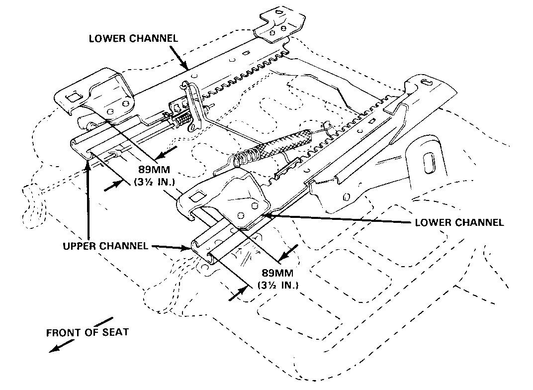
5. Release the fore/aft adjustment handle and move the adjuster tracks so that the seat is in the full-forward position. The lower channels should be in the extreme rearward position for the seat to be in the full-forward position. See Illustration.
6. Visually check that both tracks are in the full forward position. Full-forward position may be verified by measuring the distance between the forward ends of the upper and lower channels on both the inboard and outboard sides. The measurement should be approximately 89 mm (3-1/2 inches) and should not vary by more than two (2) mm. See Illustration.
7. Once the seat adjuster mechanism has been verified to be locked in the full-forward position, carefully place the seat assembly back into the vehicle and over the seat mounting studs.
IMPORTANT: The fore/aft adjustment handle must NOT be released until the rear seat mounting nuts have been tightened. If the fore/aft adjustment handle is inadvertently released before the rear seat mounting nuts are tightened, the seat must be removed from the vehicle and the adjuster mechanism re-positioned to the full-forward, locked position.
8. Install the rear seat mounting nuts and tighten to 29 N.m (21 ft. lbs.)
9. Release the adjuster handle and move the seat rearward far enough to gain access to the front seat mounting studs, but not all the way back against the rear stops. Release the adjuster handle and verify that both sides of the seat adjuster locking mechanism are fully engaged by visually inspecting the locking mechanism and by pushing the seat forward and rearward on the outboard side.
IMPORTANT: Use care when pushing the seat rearward. If the seat is pushed forcefully into the rear stops before all four mounting nuts are installed and tightened, the seat may have to be removed again to insure proper alignment of the adjuster mechanism.
10. Install the front seat mounting nuts and tighten to 29 N.m (21 ft.lbs.).
11. Verify correct function by sitting in the seat and moving the seat to several fore/aft positions and checking for any fore/aft motion after the adjuster handle is released.
12. Re-install the four (4) plastic nut covers, and the outboard track cover.
13. Repeat the above procedure (steps 1-12) for the passenger's side seat.
Use the most applicable Labour Operation and Time from the Canadian Labour Time Guide.
1. POSITION THE SEAT IN FULL-FORWARD POSITION (LOWER CHANNELS IN MAXIMUM REARWARD POSITION).
2. MAKE SURE THAT THE LOCKING PLATES ON BOTH SIDES ARE FULLY ENGAGED WITH THE "TEETH" ON THE LOWER CHANNELS.
WHEN SEAT IS IN CORRECT, FULL-FORWARD POSITION, THE DISTANCE BETWEEN THE FRONT ENDS OF THE LOWER AND UPPER CHANNELS SHOULD BE APPROXIMATELY 89MM (3 1/4 IN) AND SHOULD NOT VARY BY MORE THAN 2MM SIDE TO SIDE.

General Motors bulletins are intended for use by professional technicians, not a "do-it-yourselfer". They are written to inform those technicians of conditions that may occur on some vehicles, or to provide information that could assist in the proper service of a vehicle. Properly trained technicians have the equipment, tools, safety instructions and know-how to do a job properly and safely. If a condition is described, do not assume that the bulletin applies to your vehicle, or that your vehicle will have that condition. See a General Motors dealer servicing your brand of General Motors vehicle for information on whether your vehicle may benefit from the information.
