Removal Procedure
Tools Required
J 28467-360 J 28467-360 Engine Support
Fixture
- Disconnect the negative battery cable. Refer to
Caution: Unless directed otherwise, the ignition and start switch must be in the OFF or LOCK position, and all electrical loads must be OFF before servicing
any electrical component. Disconnect the negative battery cable to prevent an electrical spark should a tool or equipment come in contact with an exposed electrical terminal. Failure to follow these precautions may result in personal injury and/or damage to
the vehicle or its components.
Battery Disconnect Caution in General Information.
- Depressurize the fuel system. Refer to Fuel System Pressure Relief
in Engine Fuel.
- Remove the top half of the air cleaner assembly.
- Drain and recover the cooling system. Refer to Draining, Flushing
and Filling the Cooling System in Cooling and Radiator.
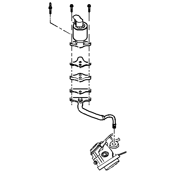
- Remove the EGR pipe from the exhaust manifold.
- Remove the drive belt. Refer to
Drive Belt Replacement
Accessory
Drive Belt Replacement .
- Remove the brake vacuum pipe at the plenum.
- Remove the power steering lines at the generator bracket.
- Remove the generator. Refer to Generator in Charging System.
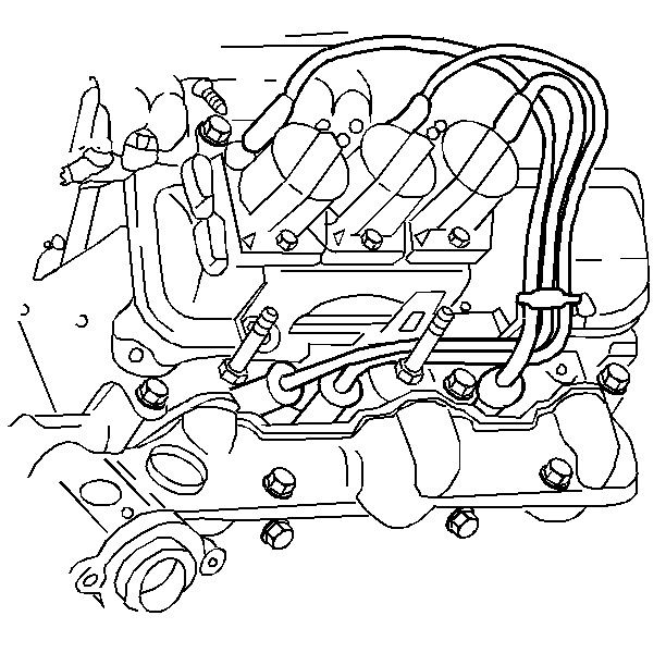
- Remove the secondary ignition wires from
the spark plugs.
Remove the secondary ignition wires from the harness at the plenum.
- Next, remove the following components at the same time:
| • | Electronic ignition coil and module assembly |
| • | EVAP canister purge solenoid |
- Remove the following upper engine wiring connectors:
| • | Throttle Position (TP) sensor |
| • | Engine Coolant Temperature (ECT) sensor |
| • | Camshaft Position (CMP) sensor |
- Remove the following vacuum lines:
| • | Fuel Pressure Regulator |
- Remove the MAP sensor from the upper intake manifold.
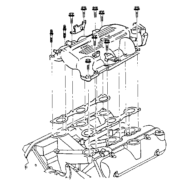
- Remove the upper intake manifold bolts.
- Remove the upper intake manifold.
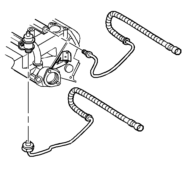
- Remove the fuel lines at the fuel rail
and the bracket.
- Install the J 28467-360
J 28467-360.
- Remove the engine mount assembly. Refer to
Engine Mount Replacement
Engine Mount Replacement .
- Remove the power steering mounting bolts. Support the pump aside.
Refer to Power Steering Pump in Power Steering Gear and Pump.
- Remove the coolant inlet pipe from the coolant outlet housing.
Refer to Cooling and Radiator.
- Remove the coolant by-pass at the coolant pump and the cylinder
head. Refer to Cooling and Radiator.
- Remove the radiator hose at the coolant outlet housing.
- Remove the coolant outlet housing. Refer to Cooling and Radiator.
- Remove both of the valve rocker covers. Refer to
Valve Rocker Arm Cover Replacement
Valve Rocker Arm Cover Replacement (Left Side).
Important: Retain the washers in the same orientation on the center bolts.
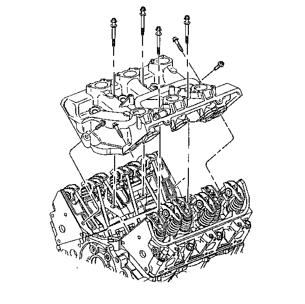
- Remove the lower intake manifold bolts.
- Remove the lower intake manifold.
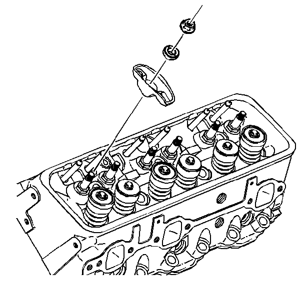
- Loosen the rocker arms.
Important: Keep the pushrods in order. The pushrods must be installed in the original
position.
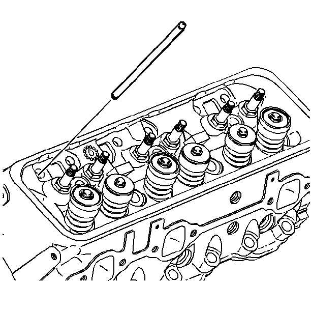
- Remove the pushrods.
- Remove the intake gasket.
- Inspect the flatness of the inlet flanges.
- Clean the following items:
| • | Gasket material from the mating surfaces |
| • | Excess RTV sealant from the front and the rear ridges of the cylinder |
| • | Sealing surfaces with degreaser |
Installation Procedure
- Place a 2-3 mm bead of GM RTV sealer P/N 1052917,
or equivalent on each ridge where the front and the rear of the intake manifold
contact the block.
- Install the intake manifold gasket.

- Install the pushrods.
| 3.1. | Install the pushrods in their original location. |
| 3.2. | Coat the ends of the pushrods with prelube GM P/N 1052356, or
equivalent. |
| 3.3. | Intake pushrods are marked yellow and are 5 3/4 in
long. |
| 3.4. | Exhaust pushrods are marked green and are 6 in long. |
| 3.5. | Ensure that the pushrods seat in the lifter. |

- Install the rocker arm bolts.
Tighten
Tighten the bolts to 10 N·m (89 lb in).
Notice: Use the correct fastener in the correct location. Replacement fasteners
must be the correct part number for that application. Fasteners requiring
replacement or fasteners requiring the use of thread locking compound or sealant
are identified in the service procedure. Do not use paints, lubricants, or
corrosion inhibitors on fasteners or fastener joint surfaces unless specified.
These coatings affect fastener torque and joint clamping force and may damage
the fastener. Use the correct tightening sequence and specifications when
installing fasteners in order to avoid damage to parts and systems.

- Install the lower intake manifold.
- Install the lower intake manifold bolts.
Tighten
- Apply sealant GM P/N 12345739 to the threads of the bolts.
- First, tighten the vertical bolts to 13 N·m (115 lb in).
- Then, tighten the diagonal bolts to 13 N·m (115 lb in).
- Install the front valve rocker cover. Refer to
Valve Rocker Arm Cover Replacement
Valve
Rocker Arm Cover Replacement (Left Side).
- Install the coolant outlet housing. Refer to Cooling and Radiator.
- Install the radiator hose to the thermostat housing.
- Install the coolant inlet pipe to the thermostat housing.
- Install the coolant by-pass pipe at the coolant pump and the cylinder
head. Refer to Cooling and Radiator.
- Install the power steering pump. Refer to Power Steering Pump
in Power Steering Pump and Gear.
- Loosely, install the drive belt. Refer to
Drive Belt Replacement
Accessory Drive
Belt Replacement .
- Install the engine mount assembly. Refer to
Engine Mount Replacement
Engine Mount Replacement.
- Remove the engine support fixture.

- Install the fuel lines to the fuel rail and the bracket.

- Install the upper intake manifold.
- Install the upper intake manifold bolts.
Tighten
Tighten the bolts to 25 N·m (18 lb ft).
- Install the MAP sensor.
- Connect the following vacuum lines:
| • | Fuel Pressure Regulator |
- Install the following upper engine wiring connectors:
| • | Throttle Position (TP) sensor |
| • | Engine Coolant Temperature (ECT) sensor |
| • | Camshaft Position (CMP) sensor |
- Install the following components:
| • | EVAP canister purge solenoid |
| • | Electronic ignition coil and module assembly |
- Install the generator. Refer to Generator in Charging System.
- Install the power steering line at the generator bracket.
- Install the drive belt. Refer to
Drive Belt Replacement
Accessory Drive Belt Replacement.

- Install the secondary ignition wires to the spark plugs.
- Install the secondary ignition wires to the harness at the plenum.

- Install the EGR pipe to the exhaust manifold.
- Install the following items to the throttle body:
- Install the top half of the air cleaner assembly.
- Install the brake vacuum pipe.
- Install the cables to the throttle body.
- Fill the cooling system. Refer to Draining, Flushing and Filling
the Cooling System in Cooling and Radiator.
- Connect the negative battery cable.
- Inspect for proper fluid levels.
- Check for leaks.


