Tools Required
J 8087 Cylinder Bore
Checking Gauge
Disassembly Procedure
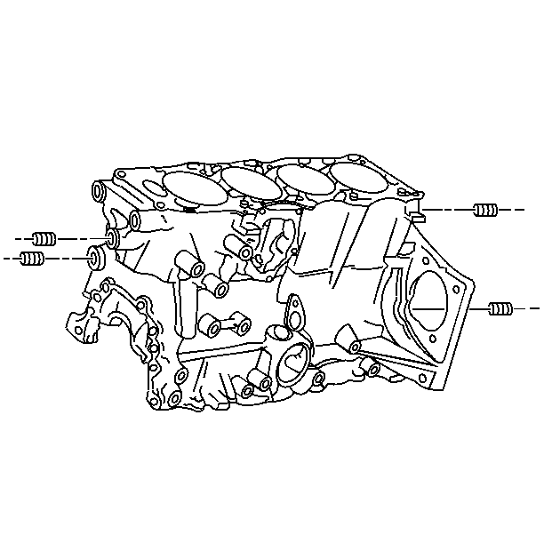
- Remove the oil passage plugs.
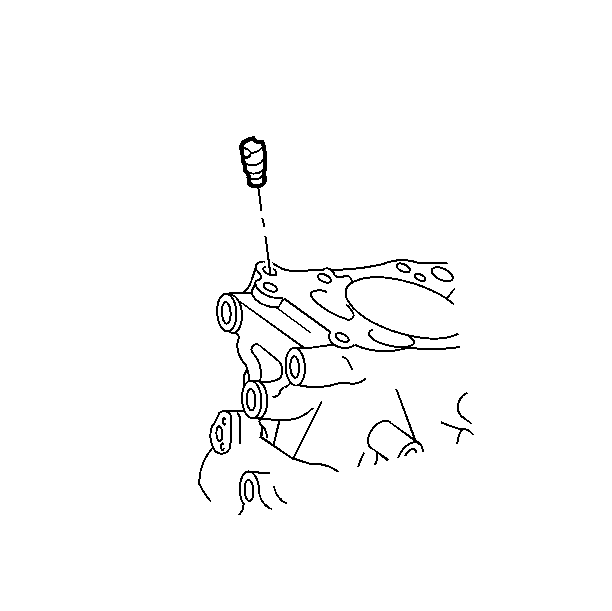
- Remove the oil flow check valve.
- Remove the crankshaft bearings, if they were not removed with
the crankshaft.
Cleaning Procedure
Notice: Caustic cleaning solution destroys the bearing material. All bearings
must be replaced after cleaning with a caustic solution. Do not clean bearing
material or aluminum parts with caustic solutions.
- Clean the following cylinder block areas:
| • | The sealing material from the mating surfaces |
| • | Boil in the caustic solution. Flush with clean hot water or steam. |
| • | Spray or wipe the cylinder bores and machine surfaces with engine
oil. |
Important: Do not use a tap to clean the cylinder head bolts holes.
- Clean the threaded holes with nylon bristle brushes.
Inspection Procedure
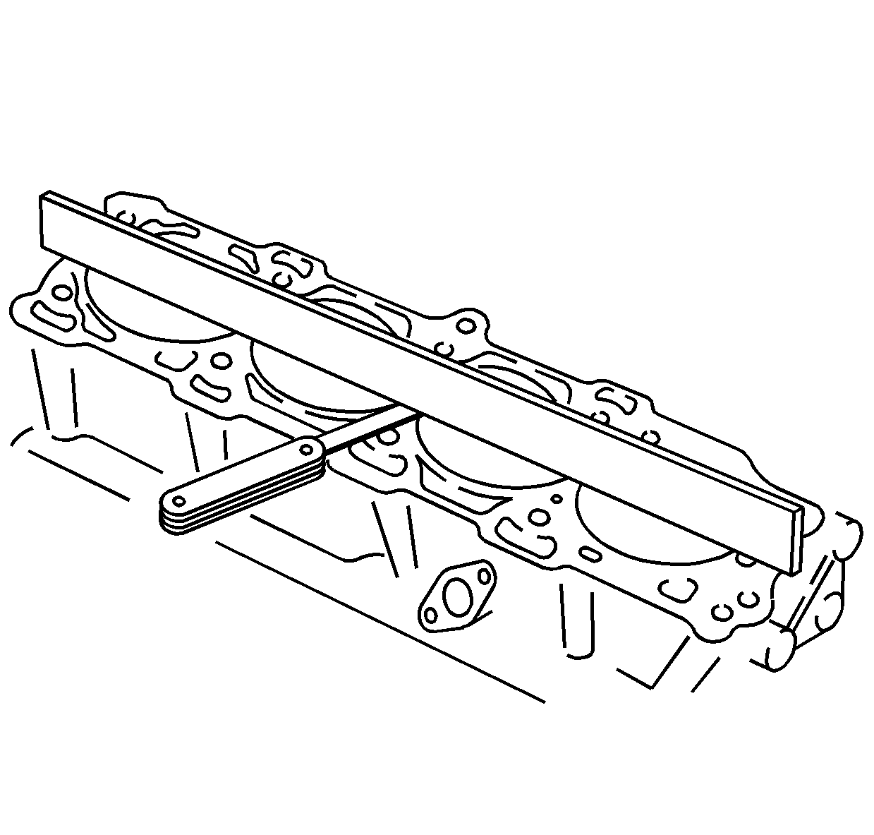
- Inspect the desk surface for flatness. Use a straight edge and a feeler
gauge. The flatness specification is a maximum of 0.076 mm (0.003 in)
overall.
- Replace the block if the flatness measurement is more than 0.25 mm
(0.010 in). Minor irregularities may be carefully machined.
- Inspect the oil pan rail and the timing cover attaching area for
nicks. Minor irregularities may be cleaned up with a flat mill file.
Notice: A broken flywheel may result if the transmission case mating surface
is not flat.
- Inspect the transmission case mating surface.
- Temporarily install the crankshaft.
Transmission Mounting Surface Runout Measuring Procedure
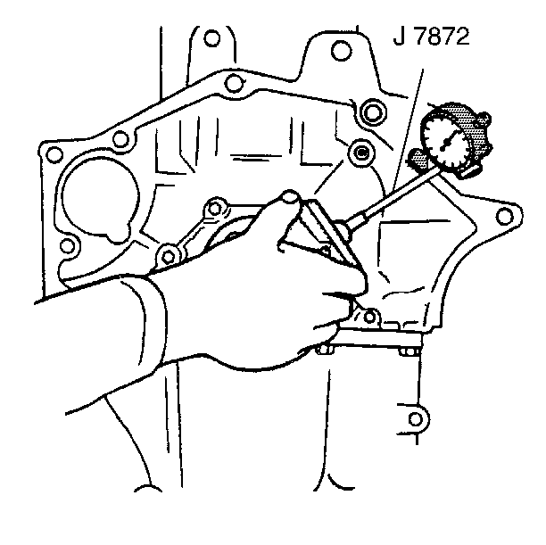
- Hold the gauge plate flat against the crankshaft flange.
- Place the dial indicator stem on the transmission mounting bolt
hole boss. Set the indicator to zero.
- Take and record the readings obtained on the remaining transmission
mounting bolt hole bosses. Measurements should not vary more than 0.203 mm
(0.008 in).
- If the readings vary more than 0.203 mm (0.008 in),
check the crankshaft flange runout.
Crankshaft Flange Runout Measuring Procedure
- Place a mark on the crankshaft flange.
- Using a dial indicator with a magnetic base adapter, measure the
crankshaft flange runout by rotating the crankshaft one full turn and recording
the readings.
- Refer to Engine Specifications for allowable tolerances. If the
crankshaft flange runout is excessive replace the crankshaft. If the crankshaft
flange runout is not excessive replace the cylinder block.
Bearing Bores Measuring Procedure
Important: The following inspections as well as reconditioning, if necessary, must
be carried out with the main bearing cap installed and torqued to specification.
Ensure that the bearing caps are installed correctly, with the arrows pointing
toward the front of the engine.
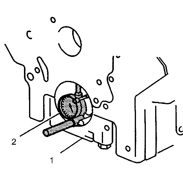
- Use a bore gauge to measure taper and out-of-round.
- Use a long steel straight edge and feeler gauge to check alignment.
- Replace the block if alignment is outside specification.
- If an examination of the outside of the bearing inserts indicates
minor high spots, they may be carefully removed.
Cylinder Bore Measuring Procedure
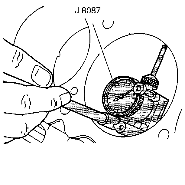
- Measure the cylinder bore. Use the J 8087
and measure for the following conditions:
- If the bore is worn beyond limits it may be re-bored, honed, and
fitted with oversize pistons.
- Leave sufficient material to allow finish honing in conjunction
with fitting the piston.
- If the bore is glazed but otherwise serviceable, break the glaze
lightly with a finishing hone and replace the piston rings.
- Rough hone with an 80 grit stone and finish hone with a 280 grit
stone.
- Make sure the honing stones are clean, sharp and straight. Move
the stone slowly up and down to produce a 45 degrees cross-hatch pattern.
- Clean the bore thoroughly with soap and hot water. Dry the bore
and use a clean towel with engine oil to scrub the cylinder bore. Continue
scrubbing the bore with clean towels and engine oil until the towel stays
clean.
- Re-measure the bore again.
Assembly Procedure

- Install the oil passage plugs. Apply pipe sealant GM P/N 1052080 or
equivalent.

- Install the oil flow check valve.


