- Lubricate the area on the armature shaft that will be under the
drive assembly lightly with GM lubricant 1960954 or equivalent.

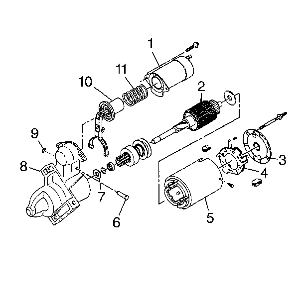
- Install the drive assembly onto the armature shaft with the pinion away
from the armature (2).
- Install the pinion stop collar onto the armature shaft (2).
- Install the new pinion stop retainer ring into the groove on the
shaft. Do not re-use the old ring.
- Connect the thrust collar (7) to the end of the shaft with the
flange toward the retainer ring. Use pliers in order to snap the pinion stop
collar over the retainer ring.
- Inspect the Bushing (SD205) or Bearing (SD255) in the drive end
housing. If damaged, replace the drive end housing. If dry, lubricate with
GM lubricant 1960954 or equivalent. Avoid excessive grease.
- Install the shift lever yoke to the drive collar, then the armature/drive/lever
assembly into the drive end housing (8).
- Install the shift lever shaft (6) through the holes in the drive
end housing (8) and shift lever, then secure with retainer. Place the return
spring onto the plunger.
- Install the solenoid (1) over the plunger by depressing the spring
and aligning to the drive end housing (8). Install the attaching screws.
- Inspect the brushes (4). If damaged or excessively worn, replace
the brushes.
- Use a soft cloth to clean the contact face of the brushes in the
frame and field assembly (5).
| 11.1. | Apply sealer GM 1050026 or equivalent to the solenoid flange where
the frame and field (5) will contact it. |
| 11.2. | Push the brushes into the brush holders and hold. |
| 11.3. | Install the frame and field assembly over the armature, aligning
properly to the drive end housing. |
| 11.4. | Release the brushes onto the commutator. Be sure all 4 brushes
move freely in the holders and are in contact with the commutator. |
- Install the brake washer onto the armature shaft
- Inspect the Bushing (SD205) or Bearing (SD255) in the commutator
end of the frame. If damaged, replace the commutator end of the frame. If
dry, lubricate with GM lubricant 1960954 or equivalent. Avoid excessive grease.
- Install the commutator end frame onto the armature shaft, aligning
with the frame and field assembly.
- Install the identification tag onto one through bolt, then two
through bolts to motor. If the through bolts have different heads, place as
noted during assembly.

Caution: Keep fingers, tools, and any other objects away from the opening in
the drive end housing while making electrical connections. The strong shifting
action of the starter solenoid can cause severe personal injury
or damage to components as the drive pinion moves into the cranking position.
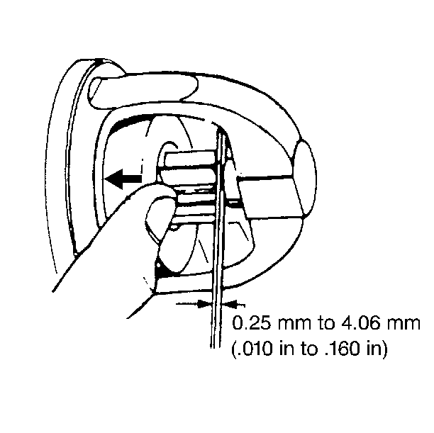
- Measure the pinion clearance as follows:
| 16.1. | Secure the starting motor in a vise or equivalent fixture so that
the opening in the drive end housing (8) is accessible for measurement. |
| 16.2. | Assure that the field lead is disconnected and insulated from
the solenoid terminal. |
| 16.3. | Connect the positive lead from a 12-volt battery to the
solenoid S terminal. Connect the negative lead from the battery to clean ground
on the motor housing. This energizes the hold-in coil. |
| 16.4. | Momentarily ground the solenoid M terminal to the motor housing.
This energizes the pull-in coil in the solenoid and causes the drive pinion
to move into cranking position. The drive pinion will stay in this position
when momentary ground is removed. |
| 16.5. | Press on the drive just enough to take up any free movement of
the pinion on the shaft. Use feeler gages to check the clearance between the
end of the pinion and the pinion stop collar. Clearance should be 0.25-4.06 mm
(0.010-0.160 in). |
| 16.6. | Disconnect the negative (ground) lead from the motor housing (drive
pinion will retract into the drive end housing), then disconnect the positive
lead from the S terminal. |
| 16.7. | If clearance is outside specifications, recheck the motor for
proper assembly and for worn or damaged parts in the shift mechanism and drive
assembly. Replace any worn parts. |
| 16.8. | Install the field lead to the solenoid terminal (1). |
Tighten
Tighten the screw to 8.5 N·m (75 lb in ).
Notice: Use the correct fastener in the correct location. Replacement fasteners
must be the correct part number for that application. Fasteners requiring
replacement or fasteners requiring the use of thread locking compound or sealant
are identified in the service procedure. Do not use paints, lubricants, or
corrosion inhibitors on fasteners or fastener joint surfaces unless specified.
These coatings affect fastener torque and joint clamping force and may damage
the fastener. Use the correct tightening sequence and specifications when
installing fasteners in order to avoid damage to parts and systems.


