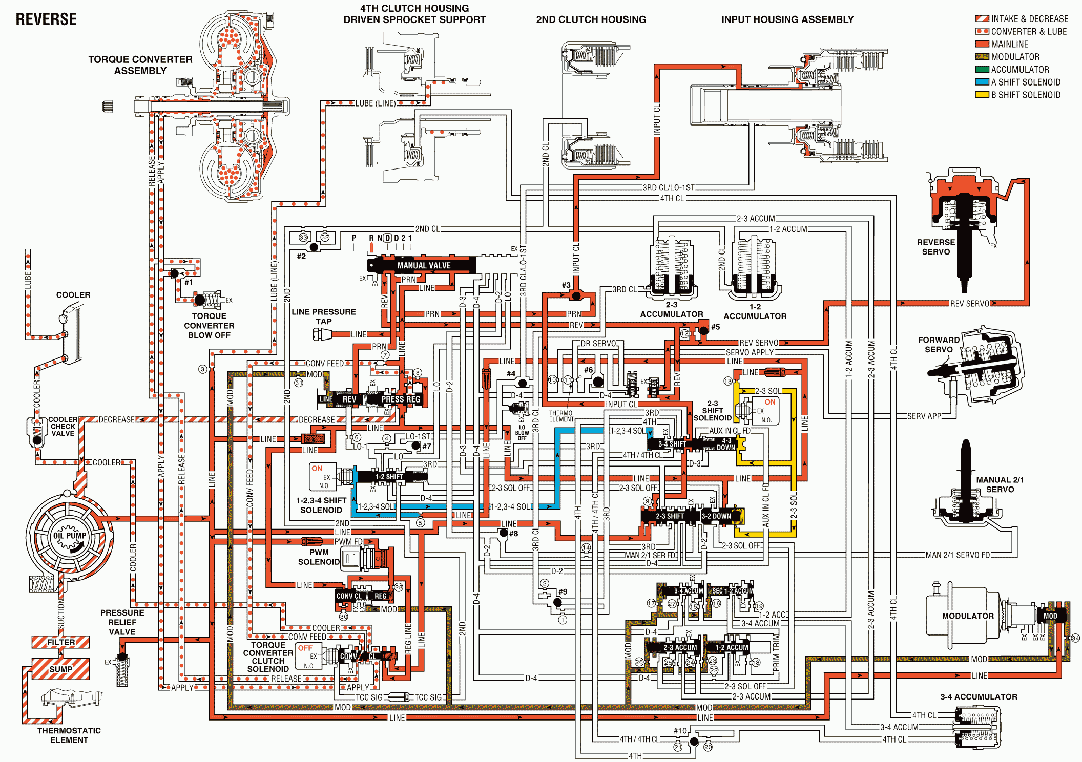
When the gear selector lever is moved to REVERSE (R), the manual valve allows line pressure to be fed through the PRN passage into the reverse fluid passage. Reverse fluid seats the #5 checkball (372). The checkball directs fluid to the reverse servo boost valve (365) and through the reverse servo feed orifice. Fluid passing through the orifice enters the reverse servo passage. This forces the reverse servo piston (44) to overcome spring pressure in order to apply the reverse band (615). Depending on the throttle position, the amount of vacuum supplied from the engine manifold to the vacuum modulator can boost to a full line pressure of 2100 kPa (305 psi), even when the engine manifold vacuum is at 0 kPa (0 psi).
Manual Valve (404)
The manual valve is moved manually to the right through the gear selector lever. This allows line pressure to enter the reverse fluid passage through the PRN fluid passage.
#5 Checkball (373)
The #5 checkball is located in the valve body (300). The checkball blocks the reverse servo feed passage, forcing reverse fluid through an orifice in the spacer plate (370) into the reverse servo passage. When the manual valve (404) is moved out of reverse, the checkball unseats. This allows reverse servo fluid to exhaust through the ball seat instead of through the orifice.
Reverse Boost Valve (367)
The reverse boost valve opens under hard acceleration (high line pressure and high throttle position). This allows reverse fluid to bypass the feed orifice and enter the reverse servo passage, which fills quickly and applies the reverse band. This prevents band slippage during abusive shifts from PARK or NEUTRAL to REVERSE.
Reverse Servo Assembly (39-49)
The reverse servo assembly applies the reverse band (615) in response to reverse servo fluid pressure feeding into the servo cover (40) side of the reverse servo piston (44).
Reverse Band Assembly (615)
The reverse band assembly wraps around the second clutch housing (617) and holds the input carrier (672) through the reverse reaction drum (669).
Reverse

