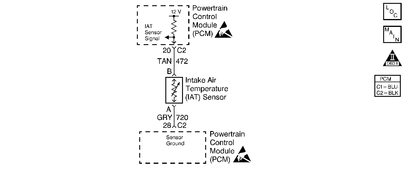
Circuit Description
The intake air temperature (IAT) sensor uses a thermistor to control the signal voltage to the Powertrain Control Module (PCM). The PCM supplies a 5 volt reference and a ground to the sensor. When the air is cold the resistance is high, therefore the IAT signal voltage will be high. If the intake air is warm, resistance is low, therefore the IAT signal voltage will be low.
Conditions for Setting the DTC
| • | Engine run time is greater than 320 seconds. |
| • | Vehicle speed is greater than 15 mph (24 km/h). |
| IAT is greater than 128°C (262°F). |
Action Taken When the DTC Sets
| • | The Malfunction Indicator Lamp (MIL) will illuminate. |
| • | The PCM will record operating conditions at the time the diagnostic fails. This information will be stored in the Freeze Frame and Failure Records buffers. |
| • | A history DTC is stored. |
| • | Coolant fan turns ON. |
| • | The PCM will default to 60°C (140°F) for intake air temperature. The scan tool will not the show the defaulted value. |
Conditions for Clearing the MIL/DTC
| • | The MIL will turn OFF after three consecutive ignition cycles in which the diagnostic runs without a fault. |
| • | A history DTC will clear after 40 consecutive warm-up cycles without a fault. |
| • | The MIL/DTCs can be cleared by using the scan tool. |
Diagnostic Aids
| • | If the vehicle is at ambient temperature, compare the IAT sensor to the ECT sensor. The IAT sensor and the ECT sensor should be relatively close to each other. |
| • | Use the Temperature vs. Resistance Values table to evaluate the possibility of a skewed sensor. Refer to Temperature vs Resistance . |
Test Description
Number(s) below refer to the step number(s) on the Diagnostic Table.
-
The Powertrain OBD System Check prompts the technician to complete some basic checks and store the freeze frame and failure records data on the scan tool if applicable. This creates an electronic copy of the data taken when the malfunction occurred. The information is then stored in the scan tool for later reference.
-
This step simulates a DTC P0113 condition. If the scan tool displays the specified value, the IAT signal circuit and the PCM are OK.
-
The replacement PCM must be reprogrammed and the crankshaft position system variation procedure must be preformed. Refer to the latest Techline procedures for PCM reprogramming and the Powertrain Control Module (PCM) for the Crankshaft Position System Variation Procedure .
Step | Action | Value(s) | Yes | No |
|---|---|---|---|---|
Was the Powertrain On-Board Diagnostic (OBD) System Check performed? | -- | |||
2 |
Is the IAT sensor value greater than the specified value? | 128°C (262°F) | ||
3 |
Is the IAT sensor value greater than the specified value? | 128°C (262°F) | Go to Diagnostic Aids | |
Disconnect the IAT sensor electrical connector. Is the IAT sensor value below the specified value? | -30°C (-22°F) | |||
5 | Replace the IAT sensor. Is the action complete? | -- | -- | |
6 | Connect a test light to B+ and probe the IAT sensor signal circuit at the IAT sensor electrical connector terminal. Does the test light illuminate? | -- | ||
7 |
Does the test light illuminate? | -- | ||
Repair the short to ground in the IAT sensor signal circuit. Is the action complete? | -- | -- | ||
9 | Replace the PCM. Is the action complete? | -- | -- | |
10 |
Does the scan tool indicate that this diagnostic ran and passed? | -- | ||
11 | Check if any additional DTCs are set. Are any DTCs displayed that have not been diagnosed? | -- | Go to applicable DTC table | System OK |
