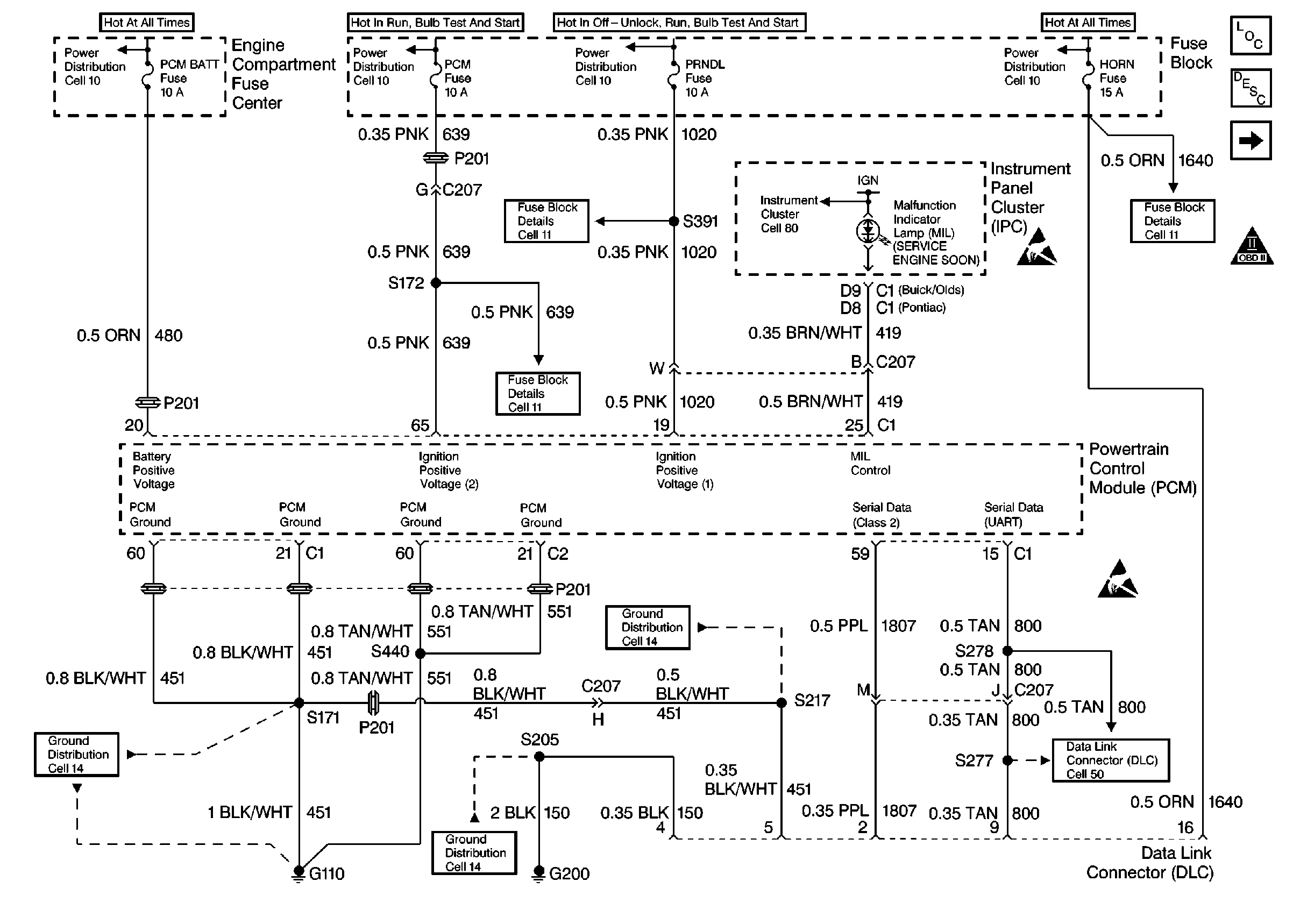
Refer to
Power, Ground, MIL, and DLC

.
Circuit Description
The Theft Deterrent System, called a Passlock System, is designed to prevent vehicle theft by disabling the engine unless the Passlock cylinder is correctly engaged by a mechanical key. The passlock System utilizes four components for theft detection, the lock cylinder, ignition switch, electronic instrument panel cluster (IPC), and the Powertrain Control Module (PCM).
When starting the engine, the PCM looks for a password from the Instrument Panel Cluster (IPC) through the UART serial data circuit. If the password is not recognized or not present, the PCM will disable the engine. There are two modes of tamper detection:
| • | Short Tamper Mode - Engine may start and stall quickly. The Theft System telltale will flash on the IPC for 4 seconds. |
| • | Long Tamper Mode (more than three starting attempts or an invalid password is received) - the engine is disabled for at least 10 minutes and the Theft System telltale will flash on the IPC for the 10 minutes. |
After the vehicle has passed theft detection, the PCM will continue normal engine operation. Additional information can be found in Section 9D, Theft Deterrent Systems.
Conditions for Setting the DTC
| • | An unrecognized or no password is sent to the PCM from the IPC. |
| • | A bad timing cycle sent from the IPC to the PCM |
Action Taken When the DTC Sets
| • | The PCM will not illuminate the malfunction indicator lamp (MIL). |
| • | The PCM will store conditions which were present when the DTC set as Failure Records data only. This information will not be stored as Freeze Frame data. |
Conditions for Clearing the MIL/DTC
| • | A History DTC will clear after 40 consecutive warm-up cycles have occurred without a malfunction. |
| • | The DTC can be cleared by using the scan tool Clear Info function. |
Diagnostic Aids
| • | An intermittent may be caused by a poor connection, rubbed through wire insulation, or a wire that is broken inside the insulation. |
| • | Any circuit that is suspected as causing the intermittent complaint should be thoroughly checked for backed out terminals, improper mating, broken locks, improperly formed or damaged terminals, poor terminal to wiring harness. |
| • | Additional can be found in section 9D Theft Deterrent Systems. |
Test Description
The numbers below refer to the step numbers on the Diagnostic Table.
-
An IPC theft deterrent DTC being set would indicate that the Passlock System is faulty and not sending a password to the PCM. Refer to Section 9, Theft Deterrent System.
-
After any Passlock System parts have been replaced, the PCM must relearn the Password from these components. Refer to Section 6E3.
-
The UART serial data circuit must be OK so the IPC can send the password information to the PCM.
-
Replacement PCM must be reprogrammed. Refer to the latest Techline information for programming procedures.
Step | Action | Value(s) | Yes | No |
|---|---|---|---|---|
1 | Was the Powertrain On-Board Diagnostic (OBD) System Check performed? | -- | ||
2 |
Was an IPC or theft deterrent DTC also set? | -- | Go to applicable DTC for diagnosis | |
Were any Passlock System related components just replaced? | -- | |||
Does the engine start and continue to run? | -- | Go toElectrical Diagnosis in Section 8A | ||
Was a problem found? | -- | |||
Is the action complete? | -- | -- | ||
7 |
Does the scan tool indicate that this diagnostic ran and passed? | -- | ||
8 | Check if any additional DTC's are set. Are any DTC's displayed that have not been diagnosed? | -- | Go to applicable DTC table | System OK, refer to Diagnostic Aids |
