For 1990-2009 cars only
Removal Procedure
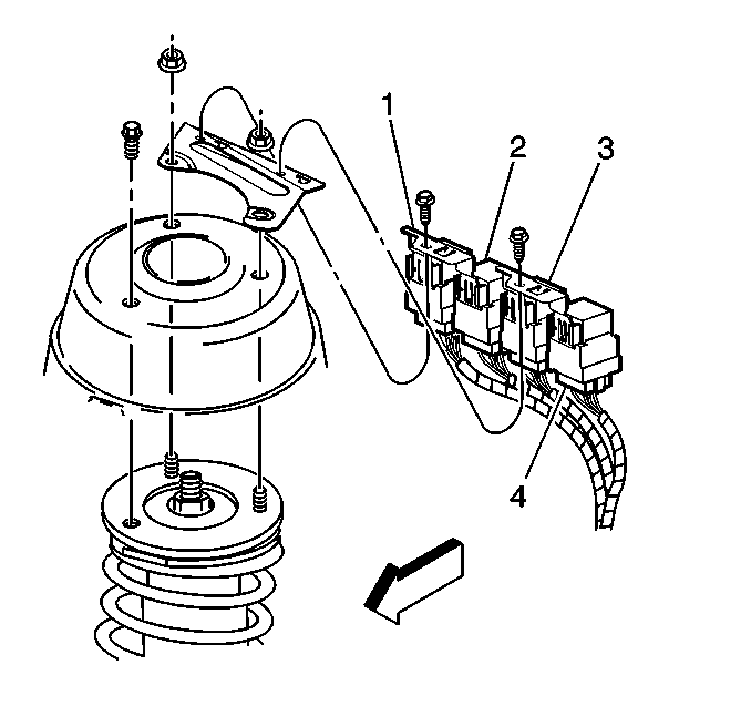
The relays in the illustration are described in the following order:
| • | (1) A/C compressor clutch relay |
| • | (2) Fuel pump relay |
| • | (3) Cooling fan relay |
| • | (4) Blower motor relay |
- Remove the appropriate relay from the bracket.
- Remove the electrical connector from the appropriate relay.

Installation Procedure
The relays in the illustration are described in the following order:
| • | (1) A/C compressor clutch relay |
| • | (2) Fuel pump relay |
| • | (3) Cooling fan relay |
| • | (4) Blower motor relay |
- Install the electrical connector to the appropriate relay.
- Install the appropriate relay to the bracket

