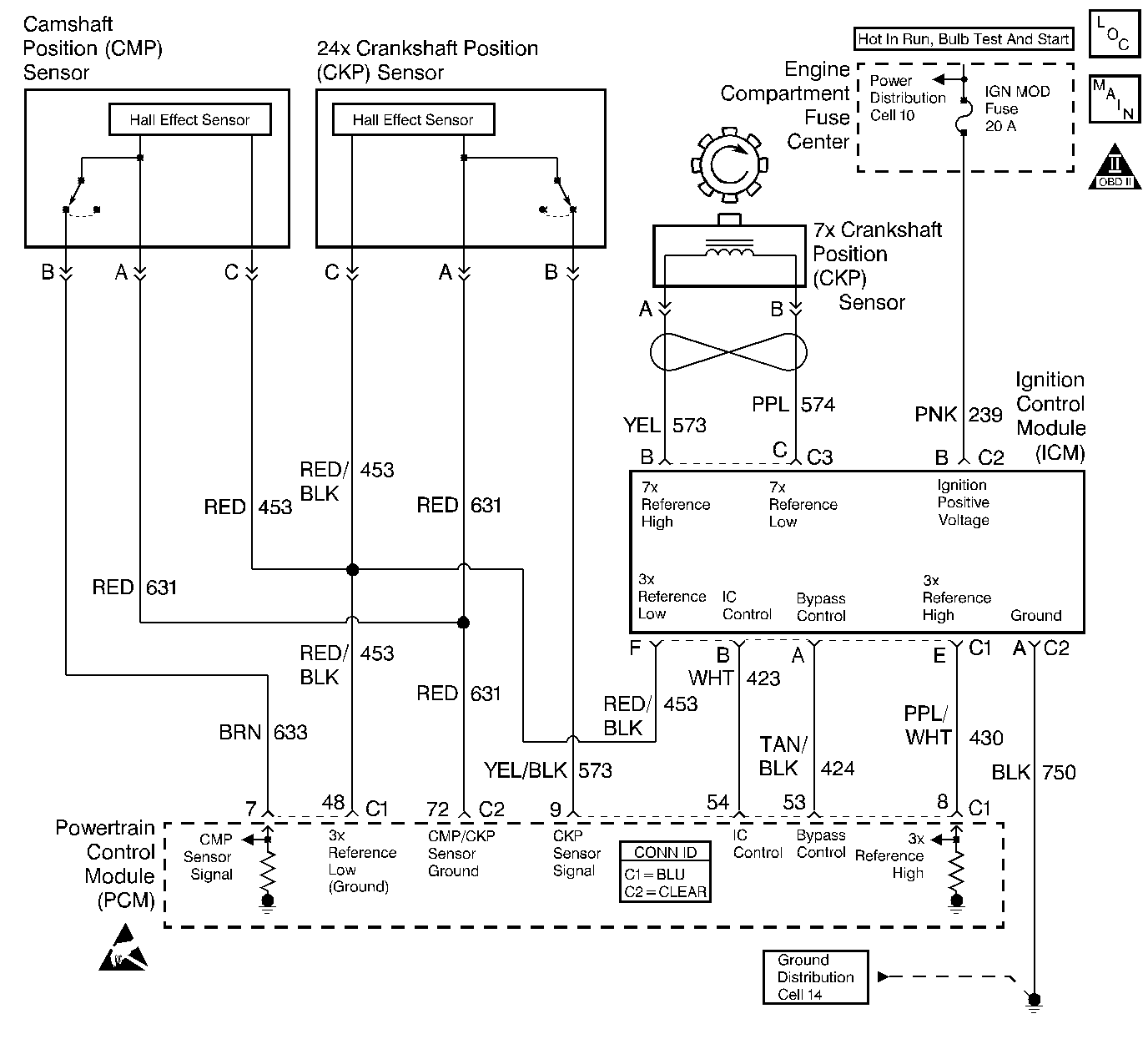
Diagnostic Aids
For diagnosis of the instrument panel, perform the System Check in the Instrument Panel Cluster (IPC) Microprocessor.
Check for the following conditions:
| • | Poor connection at PCM. Inspect harness connectors for backed out terminals, improper mating, broken locks, improperly formed or damaged terminals, and poor terminal to wire connection. |
| • | Damaged harness. Inspect the wiring harness for damage. |
Test Description
The number below refers to the step number on the Diagnostic Table:
-
This vehicle is equipped with a PCM which utilizes an Electrically Erasable Programmable Read Only Memory (EEPROM). When the PCM is replaced, the new PCM must be programmed. Refer to Powertrain Control Module Replacement/Programming .
Step | Action | Value(s) | Yes | No |
|---|---|---|---|---|
1 | Was the Powertrain On Board Diagnostic (OBD) System Check performed? | -- | ||
2 | Are any DTCs set? | -- | Go to Applicable DTC | |
3 | Install scan tool, monitor engine RPM. Does scan tool engine RPM indicate approximate engine operation? | -- | ||
4 | Monitor the Tachometer output on the Instrument Panel Cluster with engine RPM on scan tool. Do they closely match each other? | -- | ||
5 | Refer to Data Link Connector Diagnosis for diagnosing Serial Data circuit. Was a problem found? | -- | ||
6 | Refer to Instrument Cluster System Check in Instrument Panel, Gauges and Console to diagnose the Tachometer. Was a problem found? | -- | ||
7 | Install scan tool to known good vehicle and monitor engine RPM. Does engine RPM on scan tool indicate approximate engine operation? | -- | Go to Scan Tool Does Not Communicate with Components in Wiring System | |
|
Important: : Replacement PCM must be programmed. Refer to Powertrain Control Module Replacement/Programming .Replace the PCM. Is the action complete? | -- | -- | ||
9 | Check for proper operation of the Tachometer. Refer to Instrument Cluster System Check in Instrument Panel, Gauges and Console. Is the correct operation indicated? | -- | System OK |
