Air Conditioning (A/C) Refrigerant Pressure Sensor Replacement 2.4L
Removal Procedure
- Disconnect the negative battery cable.
- Disconnect the electrical connection at the sensor (5).
- Remove the pressure sensor (5). Discard the O-ring seal.
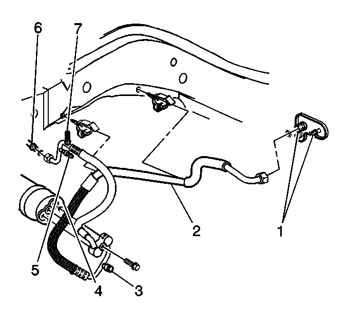
Important: The A/C system has a pressure sensor (transducer) (5) mounted onto the compressor/condenser hose assembly (2) near the condenser (6) connection. The sensor (5) performs both low and high pressure cutout functions through an input to the powertrain control module (PCM). No compressor (4) mounted switches are used. The sensor (5) mounts on to a service fitting. You can replace the sensor (5) without discharging the A/C system. For electrical information, refer to HVAC Compressor Control Schematics .
Caution: Unless directed otherwise, the ignition and start switch must be in the OFF or LOCK position, and all electrical loads must be OFF before servicing any electrical component. Disconnect the negative battery cable to prevent an electrical spark should a tool or equipment come in contact with an exposed electrical terminal. Failure to follow these precautions may result in personal injury and/or damage to the vehicle or its components.
Important: Do NOT discharge the system.
The sensor (5) mounts onto a service fitting.
Installation Procedure
- Lubricate the new O-ring seal using clean 525 viscosity refrigerant oil.
- Install the pressure sensor (5).
- Connect the electrical connection at the sensor (5).
- Connect the negative battery cable.
Install the new O-ring seal.
Notice: Use the correct fastener in the correct location. Replacement fasteners must be the correct part number for that application. Fasteners requiring replacement or fasteners requiring the use of thread locking compound or sealant are identified in the service procedure. Do not use paints, lubricants, or corrosion inhibitors on fasteners or fastener joint surfaces unless specified. These coatings affect fastener torque and joint clamping force and may damage the fastener. Use the correct tightening sequence and specifications when installing fasteners in order to avoid damage to parts and systems.
Tighten
Tighten the sensor to 5 N·m (44 lb in).
Tighten
Tighten the bolt to 16 N·m (12 lb ft).
Air Conditioning (A/C) Refrigerant Pressure Sensor Replacement 3.1L
Removal Procedure
- Disconnect the negative battery cable.
- Disconnect the electrical connection at the sensor (10).
- Remove the pressure sensor (10). Discard the O-ring (12) seal.
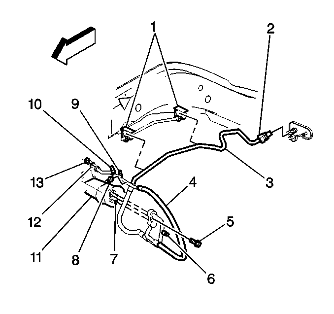
Important: The A/C system has a pressure sensor (transducer) (10) mounted onto the compressor/condenser hose assembly (4) near the condenser connection (13). The sensor performs both low and high pressure cutout functions through an input to the powertrain control module (PCM). No compressor mounted switches are used. The sensor mounts on to a service fitting. You can replace the sensor without discharging the A/C system. For electrical information, refer to HVAC Compressor Control Schematics
Caution: Unless directed otherwise, the ignition and start switch must be in the OFF or LOCK position, and all electrical loads must be OFF before servicing any electrical component. Disconnect the negative battery cable to prevent an electrical spark should a tool or equipment come in contact with an exposed electrical terminal. Failure to follow these precautions may result in personal injury and/or damage to the vehicle or its components.
Important: Do not discharge the system.
The sensor mounts onto a service fitting.
Installation Procedure
- Lubricate the new O-ring (12) seal using clean 525 viscosity refrigerant oil.
- Install the pressure sensor (10).
- Connect the electrical connection at the sensor (10).
- Connect the negative battery cable.
Install the new O-ring (12) seal.
Notice: Use the correct fastener in the correct location. Replacement fasteners must be the correct part number for that application. Fasteners requiring replacement or fasteners requiring the use of thread locking compound or sealant are identified in the service procedure. Do not use paints, lubricants, or corrosion inhibitors on fasteners or fastener joint surfaces unless specified. These coatings affect fastener torque and joint clamping force and may damage the fastener. Use the correct tightening sequence and specifications when installing fasteners in order to avoid damage to parts and systems.
Tighten
Tighten the sensor to 5 N·m (44 lb in).
Tighten
Tighten the bolt to 16 N·m (12 lb ft).
