BOSCH ANTI-LOCK BRAKE SYSTEM ACCUMULATOR SERVICE-NEW P/N

MODELS AFFECTED: 1987-1989 ALLANTES
This bulletin pertains to some 1987-1989 Allantes equipped with the Bosch Anti-Lock Brake System. The hydraulic accumulator, which is an integral part of the hydraulic unit, was previously considered non-serviceable. The accumulator was repaired by replacing the entire hydraulic unit.
This bulletin outlines the procedure to service the hydraulic accumulator without replacing the entire hydraulic unit. Accumulator service kits are available from GMSPO using part number 3520224.
Parts are expected to be available on December 5, 1988. Until then, normal part orders will not be accepted by GMSPO. Only verifiable emergency VIP orders will be accepted. SPO will make every effort to obtain parts. All parts will be placed on 400 control to waive VIP surcharges. However, the part will be shipped premium transportation at dealer's expense. All other order types will be cancelled as incorrectly ordered while the 400 control is in place.
CAUTION:
Some operations in this bulletin require that hydraulic lines, hoses, and fittings be disconnected for hydraulic accumulator service. This brake system uses a hydraulic accumulator which, when fully charged, contains brake fluid at high pressure. Before disconnecting any hydraulic lines, hoses or fittings, be sure that the accumulator is fully depressurized as described in step 1 of the service procedure in this bulletin. Failure to depressurize the hydraulic accumulator may result in personal injury and/or damage to painted surface.
SERVICE PROCEDURE
Hydraulic Unit Removal:
1. The following procedure should be used to depressurize the hydraulic accumulator.
o With ignition off, pressure switch disconnected, pump motor connector disconnected, or negative battery cable disconnected, pump the brake pedal a minimum of 25 times using approximately 50 lb. (222 N) pedal force. A noticeable change in pedal feel will occur when the accumulator is discharged.
o When a definite feel in pedal effort is felt, stroke pedal a few additional times, this will remove all hydraulic pressure from the system.
2. Consult Section 5E in Service Information Manual for disconnect and removal of the hydraulic unit.
Accumulator Removal:
1. Place hydraulic unit on bench to access bottom of hydraulic accumulator.
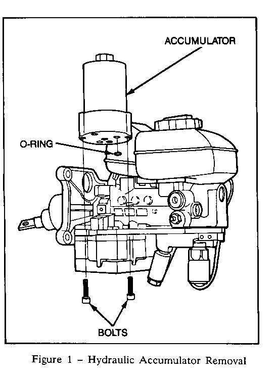
2. Remove both torque screws which hold the accumulator to the hydraulic unit, refer to Figure 1.
3. Remove the hydraulic accumulator and 0-ring seal.
CAUTION:
Do not unscrew top of accumulator from its base. The hydraulic accumulator is only serviceable by removing both screws located on the bottom of the accumulator.
Accumulator Installation:
1. The hydraulic accumulator kit (P/N 3520224) contains: hydraulic accumula- tor (1), 0-ring seal (1), torx screws (2).
IMPORTANT: Use all of the parts included in the hydraulic accumulator kit. Discard the old accumulator, 0-ring and screws.
2. Lubricate the 0-ring seal with clean brake fluid and install into hydraulic unit.
3. Make sure the mating surfaces are clean and free from any dirt.
4. Place the hydraulic accumulator onto the hydraulic unit and ensure for correct fit using the locating tabs.
IMPORTANT: Make sure 0-ring seal is in place and no damage has occurred during installation of the hydraulic accumulator.
5. Pre-torque screws to 45 ft. lbs. (57 N-m).
6. After the screws have been pre-torqued, turn screws an additional 1/4 turn.
Hydraulic Unit Installation:
1. Consult Section 5E for connection and installation of the hydraulic unit.
For warranty purposes use Labor Operation H2474 at 1.4 hours.

General Motors bulletins are intended for use by professional technicians, not a "do-it-yourselfer". They are written to inform those technicians of conditions that may occur on some vehicles, or to provide information that could assist in the proper service of a vehicle. Properly trained technicians have the equipment, tools, safety instructions and know-how to do a job properly and safely. If a condition is described, do not assume that the bulletin applies to your vehicle, or that your vehicle will have that condition. See a General Motors dealer servicing your brand of General Motors vehicle for information on whether your vehicle may benefit from the information.
