WIND NOISE AND WATER LEAK SUPPLEMENT (DIAGNOSIS/REPAIR)

WIND NOISE AND WATER LEAK SUPPLEMENT
VEHICLES AFFECTED: 1987-1988 ALLANTE -----------------
Some 1987-1988 Allantes may experience a wind noise and/or leak after all body and weatherstrip adjustments outlined in Bulletin 88-2-123 have been performed. The following service procedures are supplemental to existing procedures and will NOT repair a wind noise or water leak if the body and weatherstrip adjustments have not been performed properly. Refer to Service Bulletin 88-2-123 and Allante wind noise and water leak correction training video for necessary adjustments. It is important to identify the remaining wind noise and/or water leak using water or powder blow gun testing procedures. Once the leak has been identified, proceed to the specific service procedures below:
SECTION I
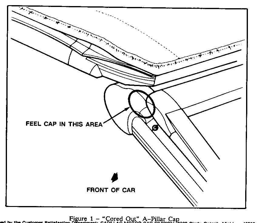
Water leak between the roof weatherstrip and the A-Pillar Cap. This may be caused by an A-Pillar Cap that is "cored out" or hollow in the upper front corner. This type of A-Pillar Cap will deflect downward when the door is closed and open a gap between the roof weatherstrip and A-Pillar Cap. Vehicles with the "cored out" A-Pillar Cap can be identified by pressing on the A-Pillar Cap in the area shown in Figure 1. If the cap is solid rubber in this area and is not flexible, proceed to Section II (the following service procedure will not apply to this vehicle). If the cap feels soft or hollow in this area, use the following repair procedure:
1. Remove hard top and place on protected surface.
2. Remove two outboard header molding screws.
3. Grasp outer edge of A-Pillar Cap and rotate up and inward to expose outside edge of header molding.
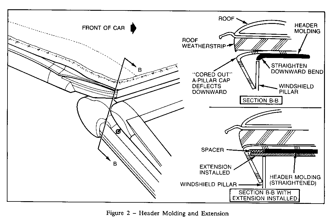
4. Reform outboard edge of existing header molding (with pliers) upward until flat (refer to Figure 2, View B-B).
5. Cut out the outboard 5" of foam under existing header molding and discard.
6. Install extension, P/N 1646636 RH and 1646637 LH, between windshield header frame-and windshield header molding (refer to Figure 2) by sliding support under the header molding until outboard screw holes in support and header molding are aligned.
7. Install spacer, P/N 1646639, on top of exposed portion of extension with Loctite 401 or equivalent (refer to Figure 2).
8. Position A-Pillar Cap over extension and header and install header molding screws.
9. Repeat steps 2-8 for the other side.
10. Install hard top.
NOTE: After extensions are installed, verify side roof rail weatherstrip to A-Pillar position.
SECTION II
Water leak between the vent frame and door opening weatherstrip. This condition is caused by interference between the vent frame cap and door opening weather-strip and/or insufficient contact between the vent frame and door opening weatherstrip. This condition results in a water leak that enters the car mid way down the windshield pillar. To repair this condition, use the following repair procedure:
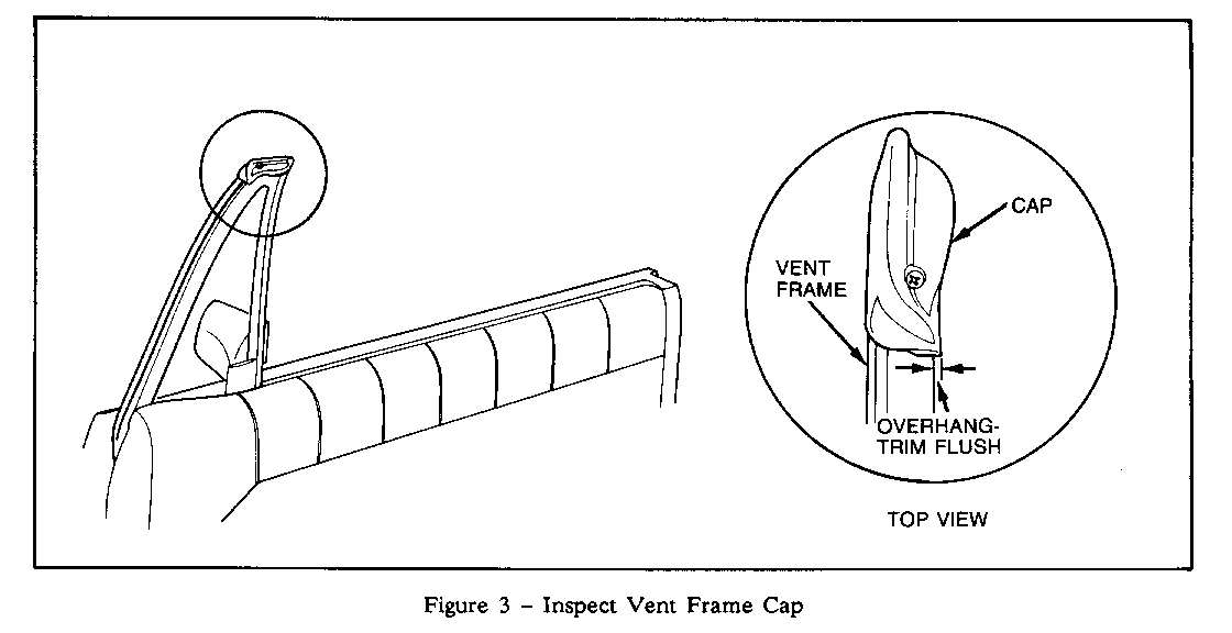
1. Open door and inspect vent frame cap for overhanging the vent frame, refer to Figure 3.
2. If overhang is present, trim vent frame cap flush with vent frame and retest for leak. If leak is present or if vent frame cap does not overhang vent frame, proceed to step 3.
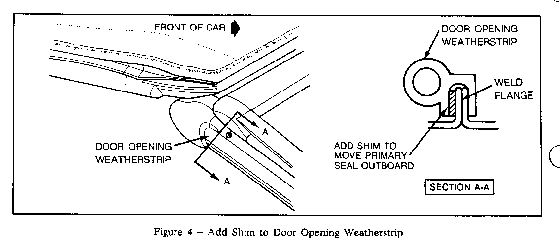
3. Fabricate a 2mm x 10mm x 250mm (or longer if needed) plastic shim.
4. Remove door opening weatherstrip along windshield pillar.
5. Install shim on outboard side of weld flange at top of windshield pillar. Retain shim in position with small amount of weatherstrip adhesive, refer to Figure 4.
6. Reinstall door opening weatherstrip.
SECTION III
Water leak between the vent frame cap and soft top side roof rail weatherstrip after all weather-strip and body adjustments have been performed properly. To repair this condition, install a latex patch kit, P/N 3634730, using the following repair procedure:
1. Inspect vent frame cap for signs of wear or cuts. If any are noted, replace the vent frame cap.
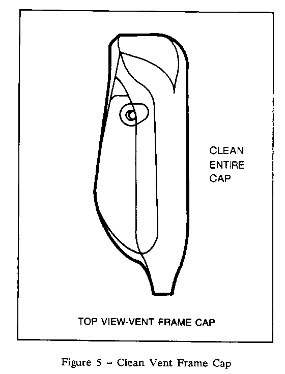
2. Clean entire surface of vent frame cap thoroughly with Naptholite 66/3 and/or isopropyl alcohol or equivalent, refer to Figure 5.
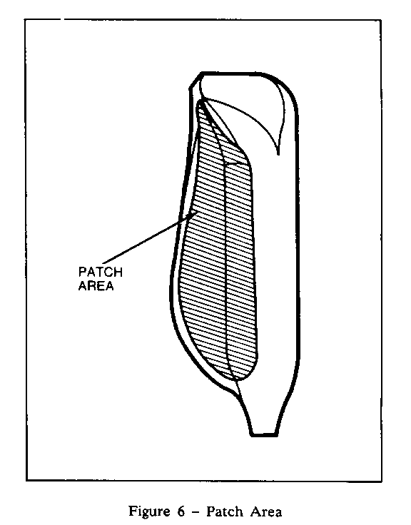
3. Fit the latex patch to the vent frame cap and outline the finished location of the patch with a marking pencil, refer to Figure 6.
4. Apply Loctite 401 adhesive or equivalent to the entire area inside the outline of the patch on the vent frame cap and spread evenly.
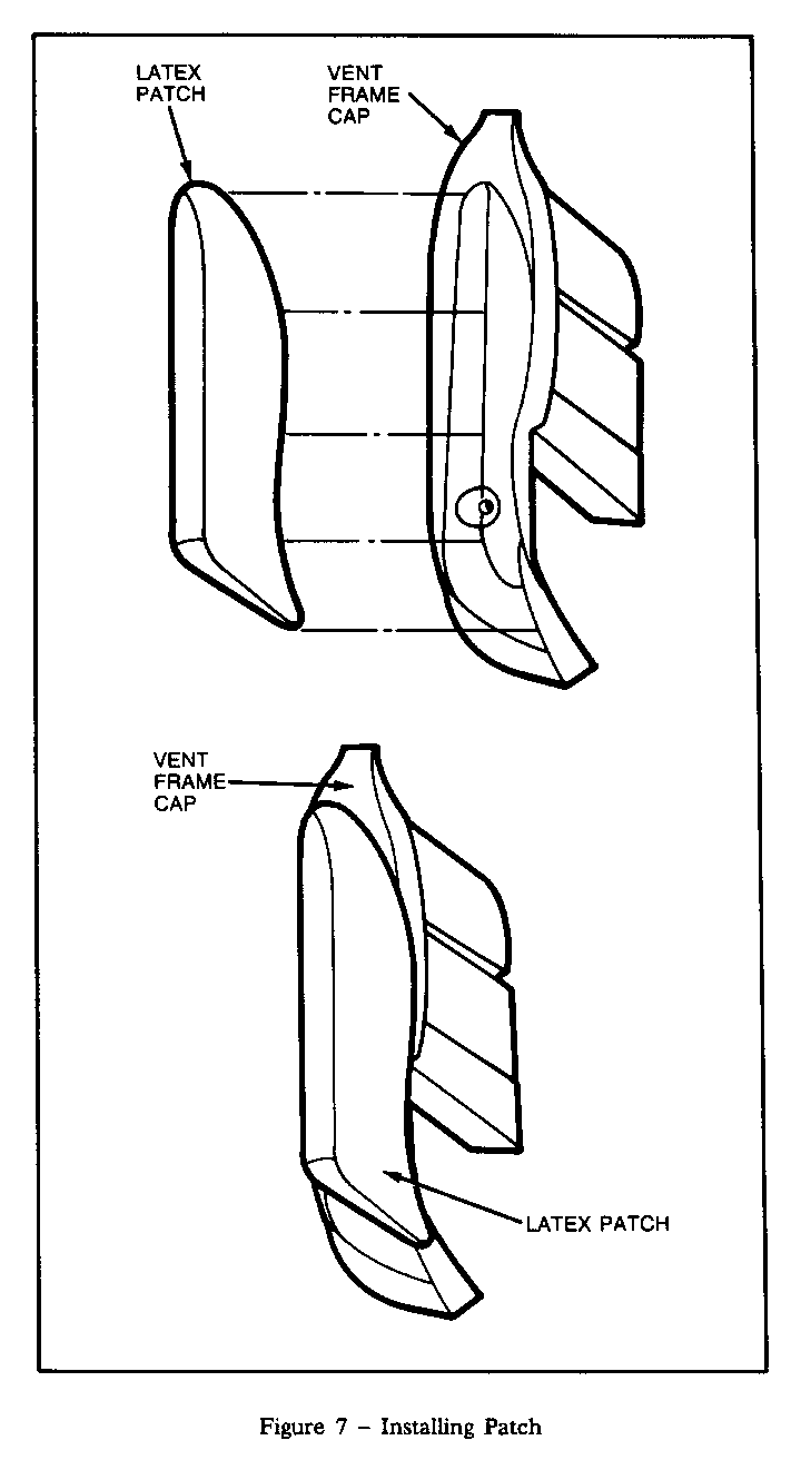
5. Position the patch inside the outlined area on the vent frame cap. Apply even pressure over entire surface of the patch and hold in place for 15-20 seconds, refer to Figure 7. Ensure all edges of the patch are firmly attached and do not extend beyond the edge of the vent frame cap. Do not close door for at least five minutes to allow the adhesive to set. Repeat for other side.
6. Inspect soft top side roof rail weatherstrip for wear. If any wear is noted, replace the side roof rail weatherstrip.
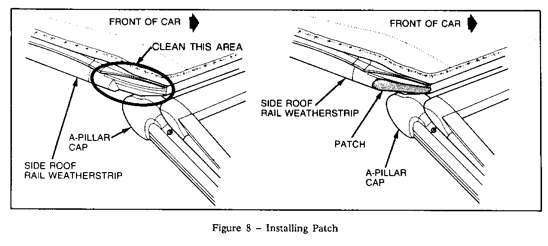
7. With soft top raised but not latched, clean surface of soft top side roof rail weatherstrip where latex patch is to be applied thoroughly with Naptholite 66/3 and/or isopropyl alcohol, refer to Figure 8.
8. Pre-fit the latex patch to the side roof rail weatherstrip to verify a smooth fit and note location, refer to Figure 8.
9. Apply Loctite 401 adhesive or equivalent to latex patch and spread evenly. Position patch to soft top side roof rail weatherstrip and apply even pressure for 15-20 seconds. Verify all edges of patch are firmly attached, do not close door or latch soft top for at least five minutes. Repeat for other side.
DISCLAIMER
"We believe this source and their material to be reliable. There may be additional manufacturers of such material. General Motors does not endorse, indicate any preference for or assume any responsibility for the products or equipment from these firsm or for any such items which may be available from other sources."
***************************************************************************** *STG DISCLAIMER*
"THE TEMPLATE DISPLAYED IN THIS SERVICE PUBLICATION IS NOT INTENDED FOR USE" (Please refer to the actual publication for an accurate "TEMPLATE" to use in this service procedure.) *****************************************************************************
General Motors bulletins are intended for use by professional technicians, not a "do-it-yourselfer". They are written to inform those technicians of conditions that may occur on some vehicles, or to provide information that could assist in the proper service of a vehicle. Properly trained technicians have the equipment, tools, safety instructions and know-how to do a job properly and safely. If a condition is described, do not assume that the bulletin applies to your vehicle, or that your vehicle will have that condition. See a General Motors dealer servicing your brand of General Motors vehicle for information on whether your vehicle may benefit from the information.
