SERVICE MANUAL UPDATE HARD & SOFT TOP BODY SERVICE

VEHICLES AFFECTED: 1990 ALLANTES WITH PHASE II CONVERTIBLE TOP
This bulletin includes Service Information Manual Section 10-9 for the 1990 Allante Phase II hard top and convertible top (RPO V4J): It should be used until the Final Edition 1990 Allante Service Information Manual is available.
SECTION 10-9 HARD TOP AND CONVERTIBLE TOP
NOTICE: When fasteners are removed, always reinstall them at the same location from which they were removed. If a fastener needs to be replaced, use the correct part number fastener for that application. If the correct part number is not available, a fastener of equal size and strength (or stronger) may be used. Fasteners that are not reused, and those requiring thread locking compound will be called out. The correct torque value must be used when installing fasteners that require it. If the above conditions are not followed, parts or system damage could result.
CONTENTS
HARD TOP General Description .........................10-9-1 Removing Hard Top ...........................10-9-1 Installing Hard Top .........................10-9-2 Header Trim Pad..............................10-9-2 Front Latch..................................10-9-3 Front Latch Mounting Bracket.................10-9-3 Front Latch Centering Pin....................10-9-4 Adjustment of Front Latch/Bracket............10-9-4 CONVERTIBLE TOP General Description .........................10-9-5 Lowering Convertible Top.....................10-9-5 Raising Convertible Top......................10-9-5 Front Latch Motor Trim Cover.................10-9-6 Front Latch Motor Asscmbly...................10-9-7 Front Latch Motor Mounting Bracket...........10-9-7 Front Latch Centering Pin....................10-9-7 Adjustment of the Front Latch Motor/Bracket..10-9-8 WINDSHIELD HEADER General Description..........................10-9-8 Upper Molding................................10-9-8 Lower Trim Panel.............................10-9-9 Lower Trim Center Cover......................10-9-9 Sunshade.....................................10-9-10 Inside Mirror................................10-9-10 Map Lamps....................................10-9-11 Front Latch and Centering Pin Strikers.......10-9-11 Adjustment of One or Both Strikers...........10-9-11 CONVERTIBLE TOP STOWAGE COVER General Description ....................10-9-12 Removal and Installation................10-9-12 Hinges..................................10-9-12 Safety Belt Retractor Cover.............10-9-14 Adjustment..............................10-9-14 TOP CONTROL PANEL General Description.....................10-9-14 Removal and Installation................10-9-14 WIRING HARNESS General Description ....................10-9-15
HARDTOP
GENERAL DESCRIPTION
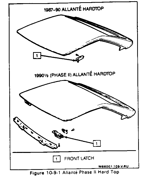
Figure 10-9-1
Some 1990 Allantes are equipped with a redesigned top assembly called the Phase II (RPO V4J). The front latch mechanism (1) is now located on the windshield header behind the sunshades. A special handle (Part #3521674) is required to operate these latches and is supplied with the car.
REMOVING HARD TOP
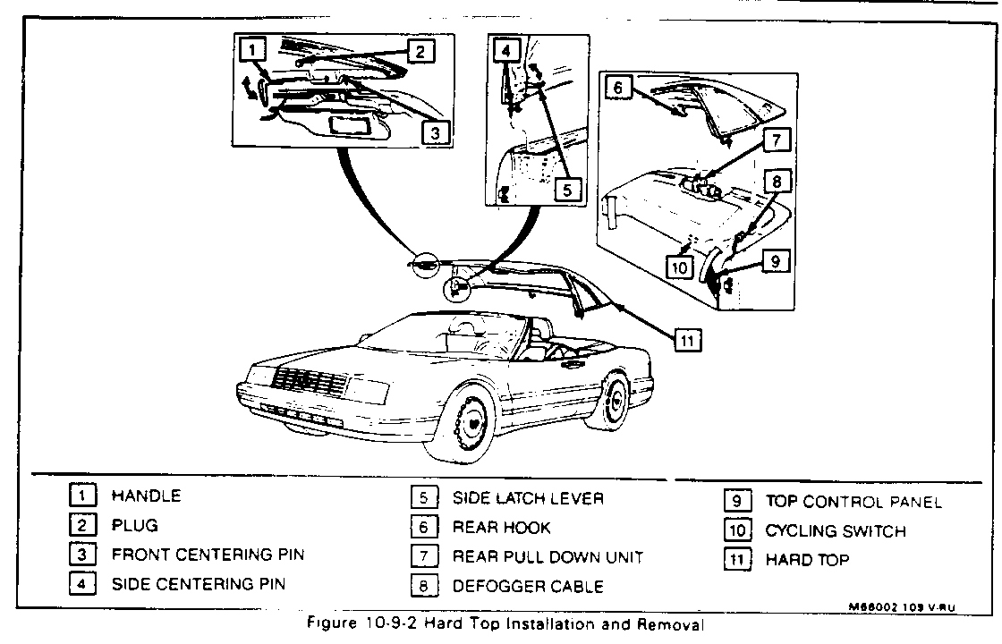
Figure 10-9-2
1. Lower both windows.
2. Make sure antenna is retracted. Turn off radio and/or cellular telephone, if so equipped.
3. Rear defogger electrical connector (8). Connector is located by the side of the hard top behind driver's seat.
4. Rotate both sunshades downward exposing plugs (2).
5. Remove both plugs to access front latch. Store plugs in center console.
6. Using handle (1) supplied, release both front latches by rotating downward.
7. Release both side latches (5) by pushing levers toward rear of car.
8. Release rear lock assembly by pulling lever (9) labeled "REAR OPEN" (located behind and to the left of the driver's seat).
9. With the aid of a helper, remove hard top assembly (11).
10. Release and raise convertible top stowage cover by pulling lever (9) labeled "COVER OPEN", Plug rear defogger cable (8) into convertible top defogger connector in stowage well.
11. If raising convertible top is desired, refer to "Raising Convertible Top" procedure in this Section.
12. If top down driving is desired, remove mini covers from pockets behind seats. Fasten both mini covers into place by sliding tab on each mini cover under quarter panel molding. Align mini cover hole with retainer pin and push down firmly, then close the cover. (Refer to Figure 10-9-8, View D)
INSTALLING HARD TOP
Figure 10-9-2
1. Lower both windows.
2. Make sure antenna is retracted. Turn off radio and/or cellular telephone, if so equipped.
3. Rotate both visors downward.
4. Lower convertiblc top, if necessary. Refer to "Lowering Convertible Top" in this Section.
5. Release and raise convertible top stowage cover by pulling lever (9) marked "COVER OPEN" (located behind and to the left of the driver's seat). Remove mini covers by lifting cover away from pin and stipping out from under quarter panel molding.
6. Disconnect rear defogger cable from convertible top connector and position it so that it will protrude through mini cover.
7. With the aid of a helper, lift hard top (11) into position over the body, making sure side hooks are forward and in position to latch. Insert front (3) and side centering pins (4) into guide holes.
8. Insert rear hook (6) through opening in convertible top stowage cover and into pull-down unit (7). Press and hold cycling switch (10) (located behind driver's seat, under storage shelf) to pull down top. Hold until a "click" is heard, which indicates that the hard top is completely seated. If top pull-down unit will not engage, the unit may need cycling. Press and hold cycling switch until a "click" is heard then release switch. The "click" is an indication that the mechanism reached the correct position.
9. Using handle (1) supplied, secure front latches by turning toward inside of car. Install plugs (2).
10. Connect rear defogger cable (8) to hard top connector located on the side of the hard top behind the driver's seat.
11. Secure side latches by pulling levers (5) toward front of the car.
HEADER TRIM PAD
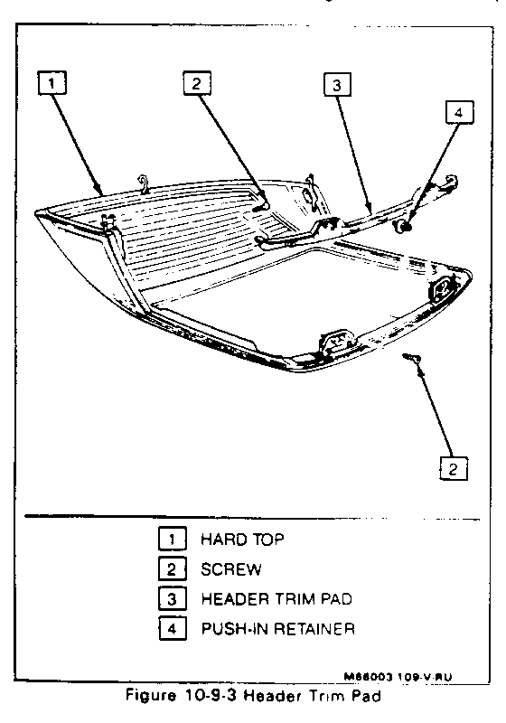
Figure 10-9-3
Remove or Disconnect
1. Hard top (1), invert, and place on a protected surface. Refer to "Removing Hard Top" in this Section. 2. Four screws (2). 3. Push-in retainer (4) in center 4. Trim pad (3).
Install or Connect
1. Trim pad (3). 2. Push-in retainer (4) in center. 3. Four screws (2). 4. Hard top (1).
FRONT LATCH
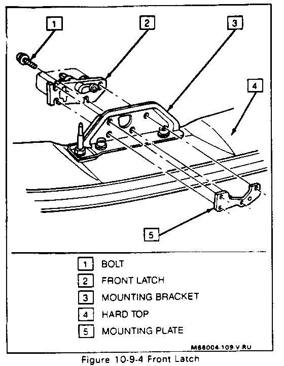
Figure 10-94
Remove or Disconnect
1. Hard top (4), invert, and place on a protected surface. Refer to "Removing Hard Top" procedure in this Section. 2. Trim pad. Refer to "Header Trim Pad" in this Section. 3. Mark position of latch (2) in relation to bracket (3). 4. Four Allen head bolts (1) using a 5 mm wrench. 5. Mounting plate (5) and latch (1).
Install or Connect
1. Align latch (2) with the marks previously made on bracket (3). 2. Position latch (2) and mounting plate (5) 3. Four Allen head bolts (1) using a 5 mm wrench. 4. Trim pad. 5. Hard top (4).
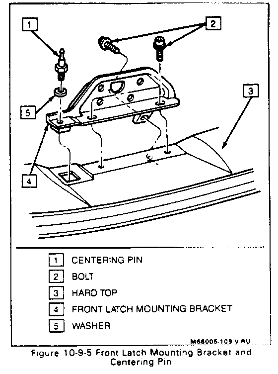
FRONT LATCH MOUNTING BRACKET
Figure 10-9-5
Remove or Disconnect
1. Hard top (3), invert, and set on protected surface. Refer to "Removing Hard Top" in this Section. 2. Trim pad. Refer to "Header Trim Pad" in this Section. 3. Mark position of bracket (4) in relation to hard top (3). 4. Three bolts (2) using a T-25 Torx driver and bracket (4).
Install or Connect
1. Align bracket (4) with scribe marks previously made. 2. Three bolts (2) using a T-25 Torx driver. 3. Trim pad. 4. Hard top (3).
FRONT LATCH CENTERING PIN
Figure 10-9-5
Remove or Disconnect
1. Hard top (3), invert, and set on protected surface. Refer to "Removing Hard Top" in this Section. 2. Centering pin (1) and washer (5) using a 13 mm wrench.
Install or Connect
1. Centering pin (1) and washer (5) using a 13 mm wrench. 2. Hard top (3).
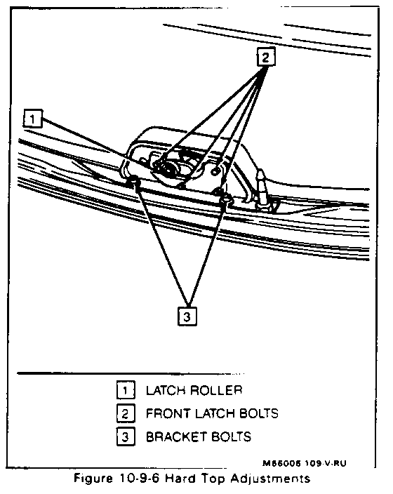
ADJUSTMENT OF FRONT LATCH/BRACKET
Figures 10-9-6 and 10-9-20
To tighten or loosen clamping force:
1. The latch roller (1) should be at end of channel in striker and hard top should fit snug against windshield header.
2. Remove trim pad. Refer to "Header Trim Pad" in this Section.
3. Loosen four bolts (2) holding front latch. Adjust one side at a time.
4. Position latch as indicated in step one and tighten bolts (2).
5. Repeat for opposite side, if necessary.
To move the hard top latch assembly right to left:
1. The latch roller (1) should be in middle of stroker opening when latch is in open position
2. Remove trim pad. Refer to "Header Trim Pad" in this Section.
3. Loosen bolts (3) holding bracket to hard top. Adjust one side at a time.
4. Position bracket as indicated in step one and tighten bolts (3).
5. Repeat for opposite side, if necessary.
CONVERTIBLE TOP
GENERAL DESCRIPTION
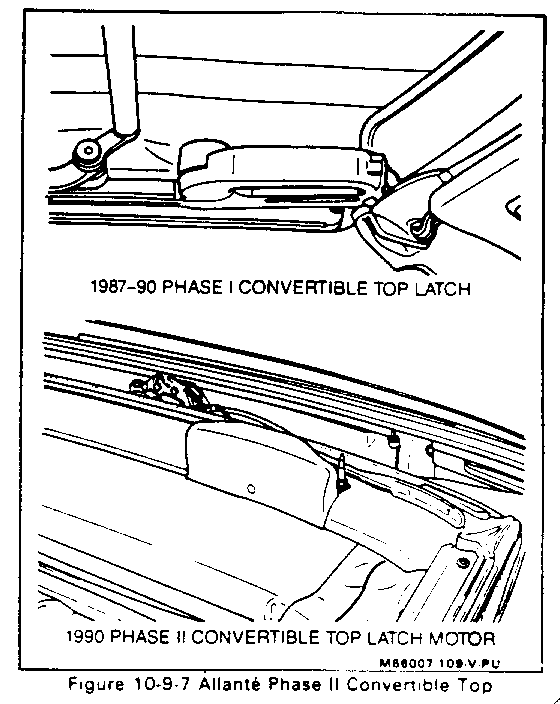
Figure 10-9-7
The Phase II convertible top has electrically operated front latches. They are activated by a switch in the top control panel, which is located behind and to the left of the driver's seat. There is a manual override knob located on the inside of trim cover. In the event of a power failure this enables the motors to be operated by hand. Spin the knob counter-clockwise to open latch, clockwise to close.
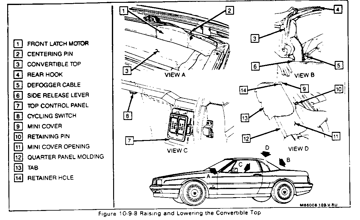
LOWERING CONVERTIBLE TOP
Figure 10-9-8
1. Lower both windows.
2. Rotate sunshades downward.
3. Release rear lock assembly by pulling lever (7) labeled "REAR OPEN" (located behind and to the left of the driver's seat).
4. Lift rear bow upward until latched, as indicated by a "click".
5. Release and raise the convertible top stowage cover by pulling lever (7) labeled "COVER OPEN". If hard top is to be installed, disconnect rear defogger cable (5) and position it so it will protrude through mini cover opening (11) of stowage cover.
6. Release front latches (1) by pressing switch (7) marked "FRONT-OPEN" located behind and to the left of the driver's seat.
7. Grasp front handle on driver's side and slowly lower convertible top (3) into stowage area. Make sure rear defogger cable (5) does not get caught under the convertible top (3).
8. If hard top is to be installed, position the rear defogger cable (5) through mini cover opening (11) in convertible top cover so that it may be connected to hard top. Firmly push cover down to lock in place, then refer to "Installing Hard Top", starting with step seven.
9. If top down driving is desired, fasten both mini covers (9) into place by sliding tab ( 13) on each mini cover under quarter panel molding (12). Align mini cover hole (14) with retainer pin (10) and push down firmly. Close stowage cover.
AISING CONVERTIBLE TOP
Figure 10-9-8
1. Lower both windows.
2. Rotate both sunshades downward
3. Release convertible top stowage cover by pulling lever (7) marked "COVER OPEN" (located behind and to the left of driver's seat)
4. Remove each mini cover (9) by lifting top edge until hole (14) disengages pin (10) Slide mini cover (9) toward center of car until free Place mini covers in pockets behind seats
5. While facing rear of car, on the driver's side, grasp lift handle and raise convertible top assembly (3) to an upright position
6. Secure front latches (1) pressing switch (7) marked "FRONT-CLOSE" located behind driver's seat. Check to be sure front bow is secured to header. If front bow is not down, the unit may need cycling. Press and hold switch in the open position until motors stop. The front latches (1)will now secure to header by pressing switch in close direction.
7. Connect rear defogger cable (5) if it is not already connected.
8. Close stowage cover. Firmly push down to lock in place.
9. Rear bow of the convertible top (3) must be unlatched from the driver's side of car. Pull rear bow forward. Then, press downward and momentariily hold the side release lever (6) (red button) located by the driver's side quarter window. Slowly push rear top toward rear of car. As soon as it has moved a few inches, lever (6) should be released.
CAUTION:
The pull-down unit will automatically activate when the rear hook is inserted. In order to prevent personal injury keep fingers and tools from under top flange as it is being installed.
12. Lower rear of top toward stowage well cover until convertible top material is unfolded, but do not engage pull-down unit. Lift rear bow halfway up to approximately a 45 degree angle and firmly swing it down to engage pull-down unit. If rear hook (4) will not engage, the pull-down mechanism may need to be cycled. The cycling switch (8) is located behind the driver's seat below the storage shelf area. Press and hold cycling switch (8) and the pull-down mechanism will cycle to the "UP" position so that the top can be latched. A "click" will be heard when mechanism reaches the correct position. Repeat step 12, as the hook will now engage and automatically pull down rear of top.
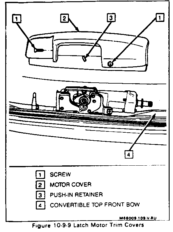
FRONT LATCH MOTOR TRIM COVER
Figure 10-9-9
Remove or Disconnect
1. Lower convertible top (4). Refer to "Lowering Convertible Top" in this Section.
2. Two screws (1).
3. Push-in retainer (3).
4. Trim cover (2). Lift outside edge, move toward center of vehicle, and lift off.
Install or Connect
1. Trim cover (2). Tilt cover to insert manual knob and set down over motor.
2. Push-in retainer (3).
3. Two screws (1).
4. Raise convertible top (4).
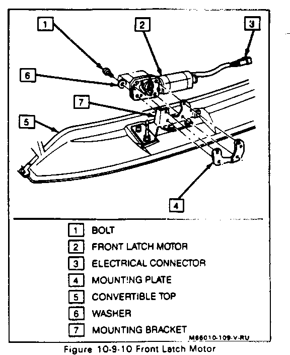
FRONT LATCH MOTOR ASSEMBLY
Figure 10-9-10
Remove or Disconnect
1. Lower convertible top (5). Refer to "Lowering Convertible Top" in this Section.
2. Trim cover. Refer to "Front Latch Motor Trim Cover" in this Section.
3. Mark position of front latch motor (2) in relation to bracket (7).
4. Electrical connector (3).
5. Four Allen bolts (1) and washers (6) using 5 mm wrench.
6. Latch motor (2) and mounting plate (4).
Install or Connect
1. Align latch motor (2) and mounting plate (4) with scribe marks previously made on bracket (7).
2. Four Allen head bolts (1) and washers (6).
3. Electrical connector (3).
4. Trim cover.
5. Raise convertible top (5).
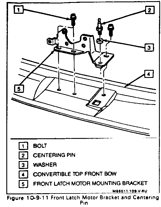
FRONT LATCH MOTOR MOUNTING BRACKET
Figure 10-9-11
Remove or Disconnect
1. Lower convertible top. Refer to "Lowering Convertible Top" in this Section.
2. Trim cover. Refer to "Front Latch Motor Trim Cover" in this Section.
3. Front latch motor. Refer to "Convertible Top Front Latch Motor Assembly" in this Section.
4. Mark position of the bracket (5) in relation to the front bow (4).
5. Four Torx head bolts (1) using a T-25 driver.
6. Bracket (5).
Install or Connect
1. Align bracket (5) with marks previously scribed on front bow (4).
2. Four Torx head bolts (1).
3. Front latch motor.
4. Trim cover.
5. Raise convertible top.
FRONT LATCH CENTERING PIN
Figure 10-9-11
Remove or Disconnect
1. Lower convertible top. Refer to "Lowering Convertible Top" in this Section.
2. Centering pin (2) and washer (3) using a 13 mm wrench.
Install or Connect
1. Centering pin (2) and washer (3).
2. Raise convertible top.
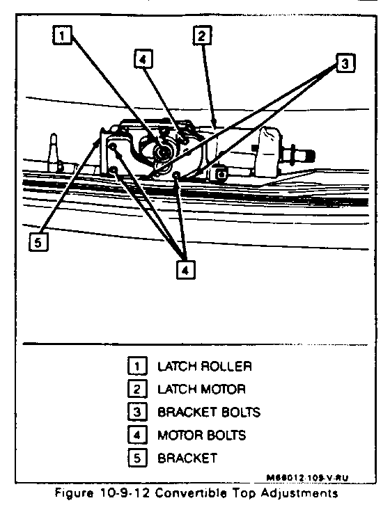
ADJUSTMENT OF FRONT LATCH MOTOR/ BRACKET
Figures 10-9-12 and 10-9-20
To tighten or loosen the convertible top front clamping force:
1. The latch motor roller (1) should be at end of the channel in striker and convertible top should fit snug against windshield header.
2. Remove trim covers. Refer to "Front Latch Motor Trim Covers" in this Section.
3. Loosen four bolts (4) holding front latch motor (2). Adjust one side at a time.
4. Position motor (2) as indicated in step one and tighten bolts (4).
5. Repeat for opposite side, if necessary.
To move latch motor assembly right or left:
1. The latch motor roller (1) should be in middle of striker opening when latch is in open position.
2. Remove trim covers. Refer to "Front Latch Motor Trim Covers" in this Section.
3. Loosen bolts (3) holding bracket (5) to convertible top front bow. Adjust one side at a time.
4. Position bracket (5) as indicated in step one and tighten bolts (3).
5. Repeat for opposite side, if necessary.
WINDSHIELD HEADER
GENERAL DESCRIPTION
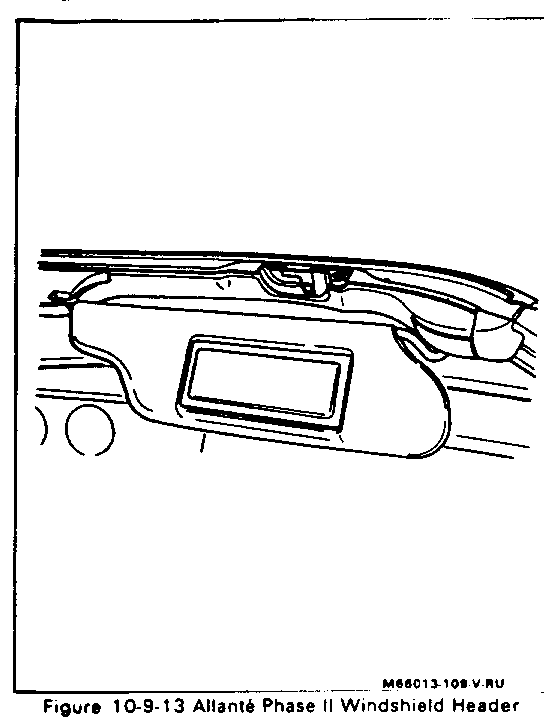
Figure 10-9-13
The Phase II windshield header has also been restyled. These changes include the relocation of the front strikers to a position behind the sunshades, the map lamps to the bottom of the mirror, and the elimination of the garage door opener provision.
UPPER MOLDING
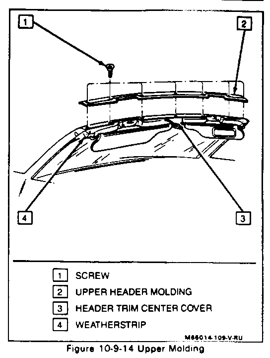
Figure 10-9-14
Remove or Disconnect
1. Hard top or lower convertible top assembly. Refer to "Hard Top" or "Convertible Top" in this Section.
2. Use release agent such as 3M 08971 or equivalent to separate weatherstrip (4) from molding (2) at each corner of header.
3. Lower trim center cover. Refer to "Lower Trim Center Cover" in this Section.
4. Screws (1) attaching molding (2) to header.
5. Carefully work molding (2) up and out from header.
Install or Connect
1. Carefully work molding (2) into header, aligning screw holes.
2. Five screws (1) securing molding (2).
3. Lower trim center cover (3).
4. Apply weatherstrip adhesive such as 3M 08011 or equivalent, to weatherstrip (4) at each comer of molding (2).
5. Wipe off excess sealer and secure hard or convertible top.
LOWER TRIM PANEL
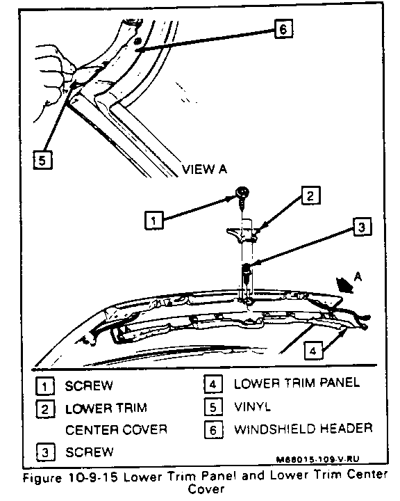
Figure 10-9-15
Remove or Disconnect
1. Hard top or lower convertible top assembly. Refer to "Hard Top " or "Convertible Top" in this Section.
2. Two screws (1) and lower trim center cover (2). Refer to "Lower Trim Center Cover" in this Section.
3. Both sunshade assemblies. Refer to "Sunshade" in this Section.
4. Upper header molding. Refer to "Upper Molding" in this Section.
5. Carefully peel back vinyl (5) attached to windshield header (6).
6. One screw (3) attaching trim (4) to center of header.
7. Trim panel (4).
Install or Connect
1. Position trim (4) and secure center screw (3).
2. Both sunshade assemblies.
3. Using adhesive such as 3M Spray General Trim Adhesive 08080 or equivalent, secure the vinyl trim (5) to the windshield header (6).
4. Upper molding.
5. Lower trim center cover (2) and secure with two screws (1).
6. Secure hard or convertible top.
LOWER TRIM CENTER COVER
Figure 10-9-15
Remove or Disconnect
1. Hard top or lower convertible top assembly. Refer to "Hard Top" or "Convertible Top" in this Section.
2. Sunshade from inboard anchor.
3. Two screws (1) and lower trim center cover (2).
Install or Connect
1. Position center cover (2).
2. Two screws (1).
3. Sunshade to inboard anchor.
4. Secure top assembly.
SUNSHADE
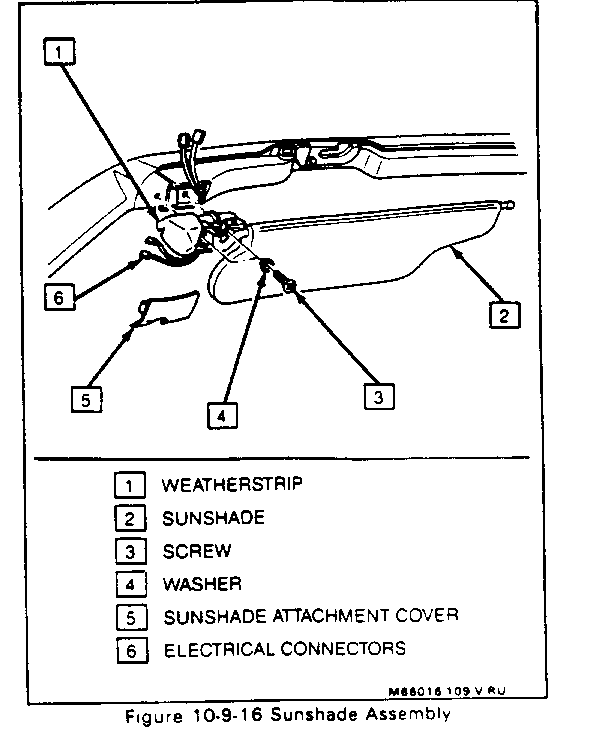
Figure 10-9-16
Remove or Disconnect
1. Hard top or lower convertible top assembly. Refer to "Hard Top" or "Convertible Top" in this Section.
2. Use release agent such as 3M 08971 or equivalent to separate weatherstrip (1) from molding at corner of header.
3. Sunshade (2) from inboard anchor.
4. Sunshade attachment cover (5). Carefully slide to the inside and lift outboard side out.
5. Two screws (3) and washers (4) at outboard anchor.
6. Two electrical connectors (6) and sunshade assembly (2).
Install or Connect
1. Two electrical connectors (6) and position sunshade (2).
2. Two screws (3) and washers (4) at outboard anchor.
3. Sunshade attachment cover (5). Slide inboard hook in position and snap the outboard side in.
4. Sunshade (2) to inboard anchor.
5. Apply weatherstrip adhesive such as 3M 08011 or equivalent, to weatherstrip (1) at corner of molding.
6. Wipe off excess sealer and secure hard or convertible top.
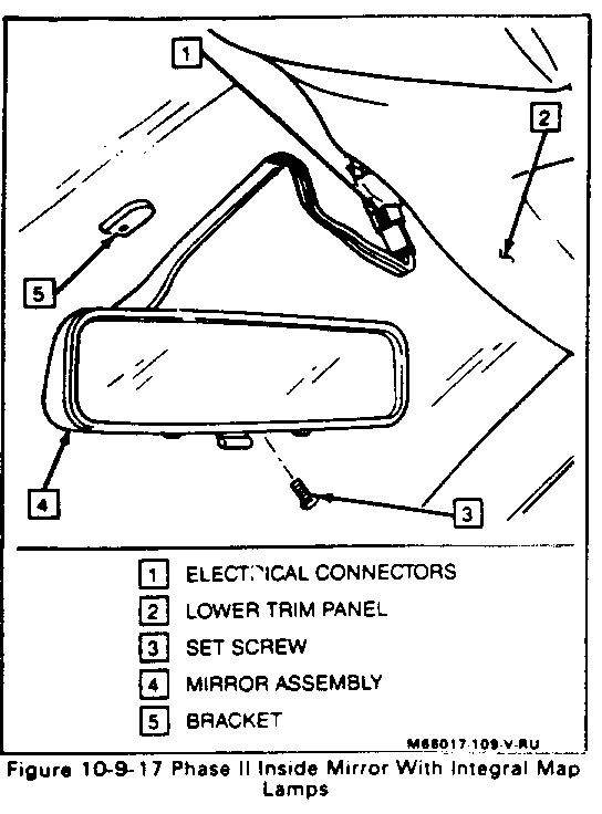
INSIDE MIRROR ASSEMBLY
Figure 10-9-17
The Phase II mirror assembly incorporates the map lamps. They are activated by a rocker switch located at the bottom of the mirror. The day/night control remains the same.
Remove or Disconnect
1. Lower trim panel (2). Refer to "Lower Trim Panel" in this Section.
2. Electrical connection (1).
3. Mirror assembly (4). Loosen Torx head set screw (3) and lift mirror off of bracket (5)
Install or Connect
1. Slide mirror (4) onto bracket (5) and tighten set screw (3).
2. Electrical connection (1).
3. Lower trim panel (2).
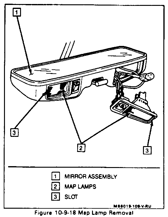
MAP LAMPS
Figure 10-9-18
Remove or Disconnect
1. Tilt mirror assembly (1) up to ease access to map lamps (2).
2. Insert a straight screwdriver into slot (3) located on outside edge of lamp and carefully pry from mirror assembly.
Install or Connect
1. Snap lamp (2) into mirror assembly (1).
2. Readjust mirror for proper vision.
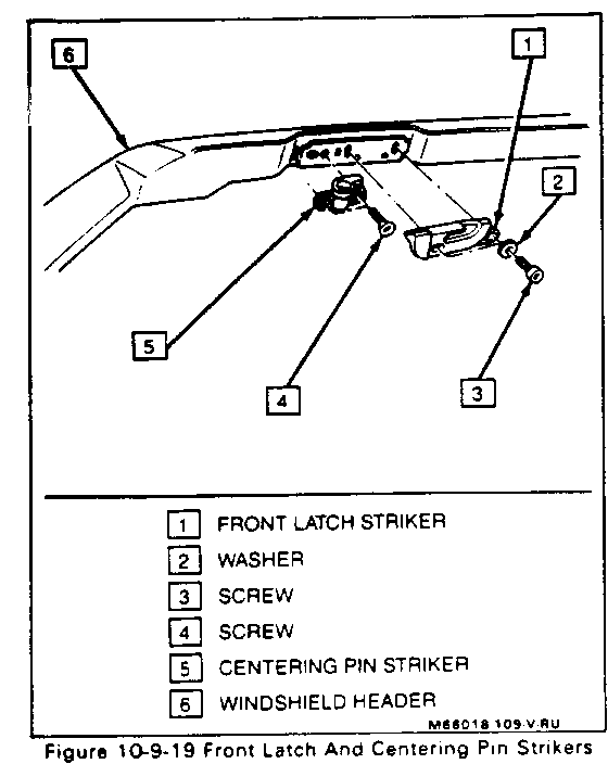
FRONT LATCH AND CENTERING PIN STRIKERS
Figure 10-9-19
Remove or Disconnect
1. Hard top or lower convertible top assembly. Refer to "Hard Top" or "Convertible Top" in this Section.
2. Lower trim center cover. Refer to "Lower Trim Center Cover" in this Section.
3. Sunsbade assembly. Refer to "Sunshade" in this Section.
4. Lower trim to expose strikers. Refer to "Lower Trim Panel" in this Section.
5. Mark position of front latch striker (1) to header (6).
6. Two screws (3) and washers (2).
7. Front latch striker (1).
8. Mark position of centering pin striker (5) to header (6).
9. Two screws (4) and centering pin striker (5).
Install or Connect
1. Position centering pin striker (5) to marks made during removal.
2. Two screws (4).
3. Position front latch striker (1) to marks made during removal.
4. Two screws (3) and washers (2).
5. Lower trim.
6. Sunshade assembly.
7. Lower trim center cover.
8. Secure hard or convertible top.
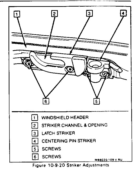
ADJUSTMENT OF ONE OR BOTH STRIKERS
Figure 10-9-20
To adjust striker right to left:
1. The latch roller on hard top or convertible top should be centered in opening (2) of striker (1) when in open position and travel to end of channel (2) when in closed position. The centering pin should freely move in and out of its striker (4) when in proper adjustment.
2. Lower trim center cover. Refer to "Lower Trim Center Cover" in this Section.
3. Sunshade assembly. Refer to "Sunshade" in this Section.
4. Lower trim to expose strikers. Refer to "Lower Trim Panel" in this Section.
5. Loosen screws (5 and 6) and adjust strikers (1 and 4) as indicated in step one.
CONVERTIBLE TOP STOWAGE COVER
GENERAL DESCRIPTION
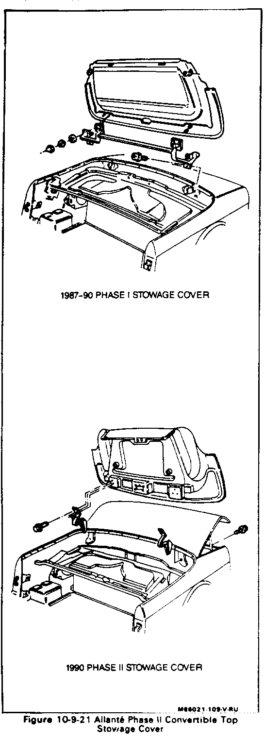
Figure 10-9-21
The Phase II convertible top stowage cover is now a hinged unit that is closed by simply, pushing down on the front of the cover. There are no longer any rollers or guides required.
REMOVAL AND INSTALLATION
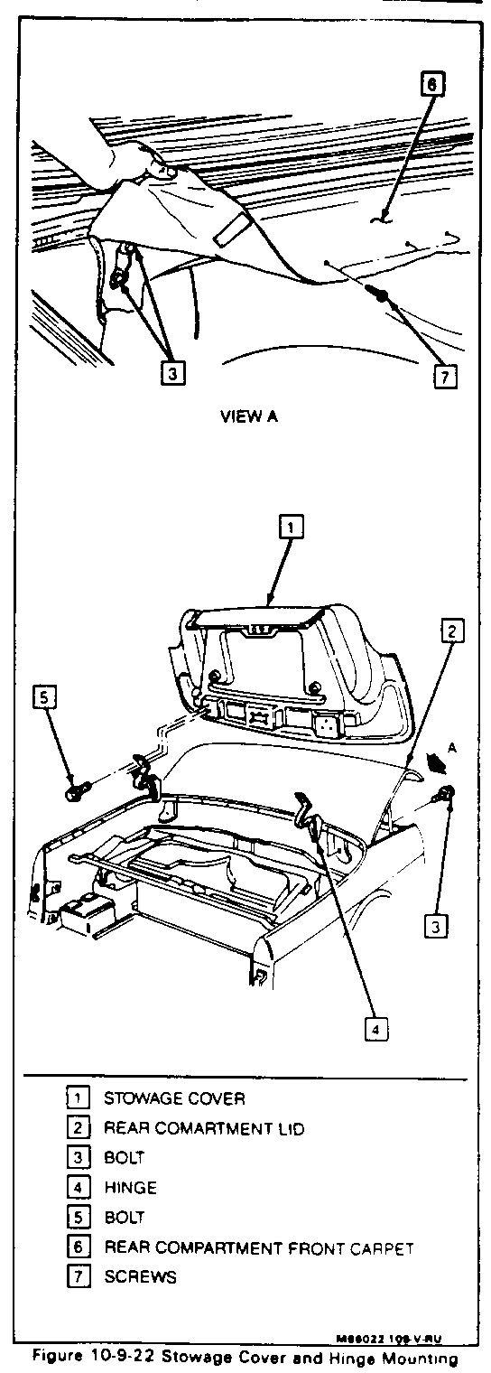
Figure 10-9-22
Remove or Disconnect
1. Hard top or lower convertible top, if necessary. Refer to "Hard Top" or "Convertible Top" in this Section.
2. Raise stowage cover (1) by pulling lever marked "COVER OPEN" located behind and to the left of driver's seat.
3. Mark position of hinge strap (4) in relation to cover.
4. Bolts and washers (5), while a helper holds the cover.
5. Stowage cover (1), with the aid of a helper
Install or Connect
1. With the aid of a helper, position cover (1) to the holes in hinge straps (4).
2. Bolts and washers (5), but DO NOT TIGHTEN.
3. Align cover with scribe marks previously made.
4. Tighten bolts (5).
5. Check for proper operation. Adjust if necessary
HINGES
Figure 10-9-22
Remove or Disconnect
1. Hard top or lower convertible top, if necessary Refer to " Hard Top" or "Convertible Top" in this Section.
2. Stowage cover (1). Refer to "Stowage Cover" in this section.
Important
Do not allow rear compartment lid to raise fully. It could contact hinges and be damaged.
3. Raise rear compartment lid (2) partially, being careful not to allow it to touch hinges (4).
4. Screws (7) from rear compartment front upper carpet (6).
5. Lift carpet to pin access to hinge bolts (3). Mark position of hinge, hinge washers, and bolts.
6. Hinge bolts and hinge.
Install or Connect
1. Position hinge (4) to scribe marks previously made.
2. Hinge bolts (3) and washers.
3. Screws (7) to rear compartment front upper carpet (6).
4. Close rear compartment lid (2).
5. Stowage cover (1).
6. Check for proper operation. Adjust if necessary.
SAFETY BELT RETRACTOR COVER
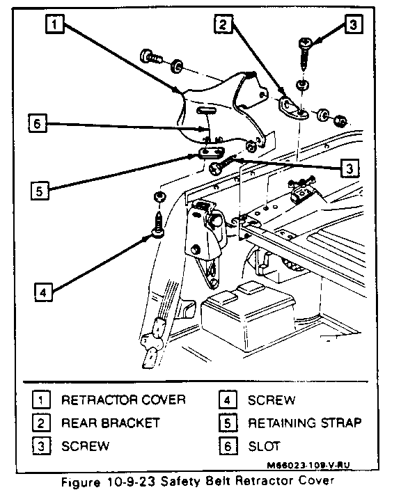
Figure 10-9-23
Remove or Disconnect
1. Hard top or lower convertible top. Refer to "Hard Top" or "Convertible Top" in this Section.
2. Raise stowage cover by pulling lever marked "COVER OPEN" located behind drivers seat.
3. Two screws (3) and lift retractor cover (1) away from vehicle.
4. To remove from safety belt, turn over, remove two phillips screws (4) and retaining strap (5), then feed belt through slot (6).
Install or Connect
1. If removed from belt, feed through slot (6), and attach retaining strap (5) with two phillips screws (4).
2. Position retractor cover (1) and two screws (2).
3. Close stowage cover and check for alignment. Adjust if necessary.
ADJUSTMENTS
To move rear of stowage cover up or down:
1. The stowage cover should be flush with quarter panel and rear compartment filler panel.
2. With the cover closed, loosen hinge bolts. Refer to "Hinge" in this Section. Adjust only one side at a time.
3. Position cover as indicated in step one and tighten bolts.
4. Repeat for opposite side, if necessary.
To move stowage cover fore and aft:
1. The latch should be centered in its striker and cover should be flush with safety belt retractor covers when closed.
2. Open cover, and loosen bolts holding hinge strap to cover. Refer to "Convertible Top Stowage Cover" in this Section. Adjust only one side at a time.
3. Position cover as indicated in step one and tighten bolts.
4. Repeat for opposite side, if necessary.
To move rear of retractor cover up or down:
1. The retractor cover, proper adjustment, should be flush with stowage cover when it is closed,
2. Loosen rear bracket. Refer to "Safety Belt Retractor Cover" in this Section.
3. Move cover up or down as indicated in step one.
4. Tighten bolt. Repeat for opposite side, if necessary.
TOP CONTROL PANEL
GENERAL DESCRIPTION
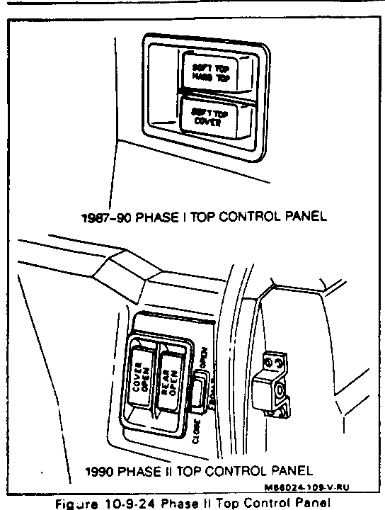
Figure 10-9-24
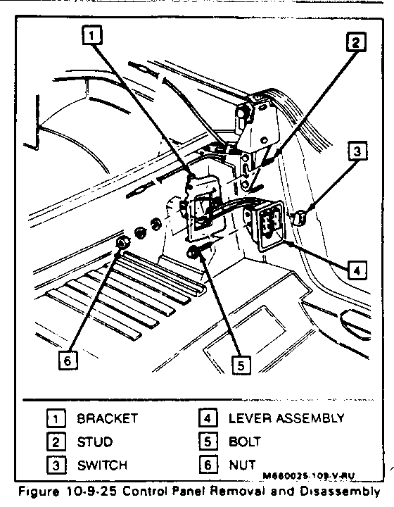
The top control panel for the Phase II has been moved to a new, more convenient location closer to the door. It is in a vertical position and incorporates a rocker switch to activate the convertible top front latch motors.
REMOVAL AND INSTALLATION
Figure 10-9-25
Remove or Disconnect
1. Left side closeout panel by simply silding toward front of vehicle.
2. Left side safety belt retractor cover. Unbolt and position out of the way. Refer to "Safety Belt Retractor Cover" in this Section.
3. Nuts (6) and control panel bracket (1).
4. If removal of lever assembly (4) is desired, disconnect cables at their respective latches and remove bolts (5).
5. If removal of latch motor switch (3) is desired, grasp switch from behind and carefully push it out of bracket (1).
Install or Connect
1. Latch motor switch (3), if removed, by snapping into bracket (1).
2. Lever assembly (4), if removed, by feeding cables through their channels, attaching to respective latches and securing latches with bolts (5).
3. Control panel bracket to studs (2) and secure with nuts (6).
4. Safety belt retractor cover.
5. Closeout panel by placing bottom edge into track and sliding back until spring clips attach to brackets on inner quarter panel.
WIRING HARNESS
GENERAL DESCRIPTION
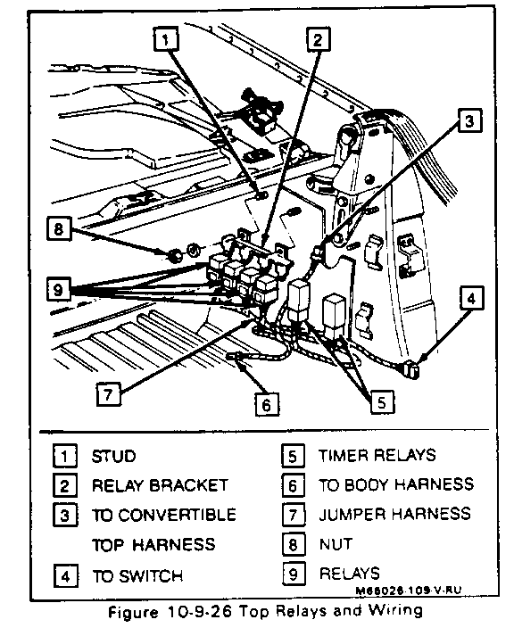
Figure 10-9-26
Since the Phase II has electrically operated front latches, there are unique new wiring harnesses and switches necessary. This wiring, is located behind the left side closeout panel. It consists of the main body wiring harness connected to a new jumper/relay harness (7) by a white two pin connector (6). The jumper hamess contains two timer relays (5) (one for each motor), and four standard relays (9) (one each for up and down, right side and left side). These are connected to a bracket (2) and are easily taken off by removing nuts (8) from studs (1). Two other connectors make up this harness. A black six pin connector (3) goes to the convertible top harness. A white 3 pin connector (4) goes to the front latch activation switch in the top control panel.
The convertible top harness runs up and along the left side of the convertible top inner structure and across the front of the top. It is secured in place with plastic retaining straps placed approximately every three inches. This harness powers both of the front latch motors.
General Motors bulletins are intended for use by professional technicians, not a "do-it-yourselfer". They are written to inform those technicians of conditions that may occur on some vehicles, or to provide information that could assist in the proper service of a vehicle. Properly trained technicians have the equipment, tools, safety instructions and know-how to do a job properly and safely. If a condition is described, do not assume that the bulletin applies to your vehicle, or that your vehicle will have that condition. See a General Motors dealer servicing your brand of General Motors vehicle for information on whether your vehicle may benefit from the information.
