Excessive Engine Noise (Install Manifold Covers)

| Subject: | Excessive Engine Noise (Install Manifold Covers) |
| Models: | 2003 Cadillac CTS Built Prior To VIN Breakpoint 30124293 |
Condition
Some customers may comment on an excessive amount of noise from the engine area. This noise may be described as a "sewing machine" or "ticking" type noise.
No DTCs are set, no driveability symptoms are noted and there are no emission concerns relative to this noise issue.
Correction
Acoustic covers, which reduce the audible noise, are available for the LH and RH engine cam covers as well as the rear intake manifold. When installed, these molded rubber, acoustic foam backed covers have demonstrated a noticeable noise reduction.
Important: Ensure all (3) acoustic pieces are properly installed for maximum noise reduction.
Installation Procedure
- Loosen the fuel filler cap in order to relieve the system pressure.
- Disconnect the negative battery cable from the battery. Refer to Battery Negative Cable Disconnect/Connect Procedure in the Engine Electrical sub-section of the Service Manual.
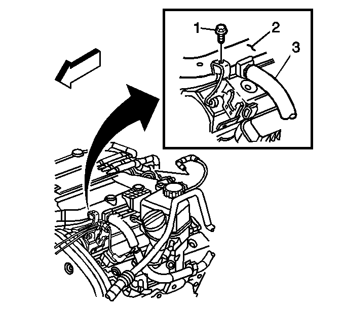
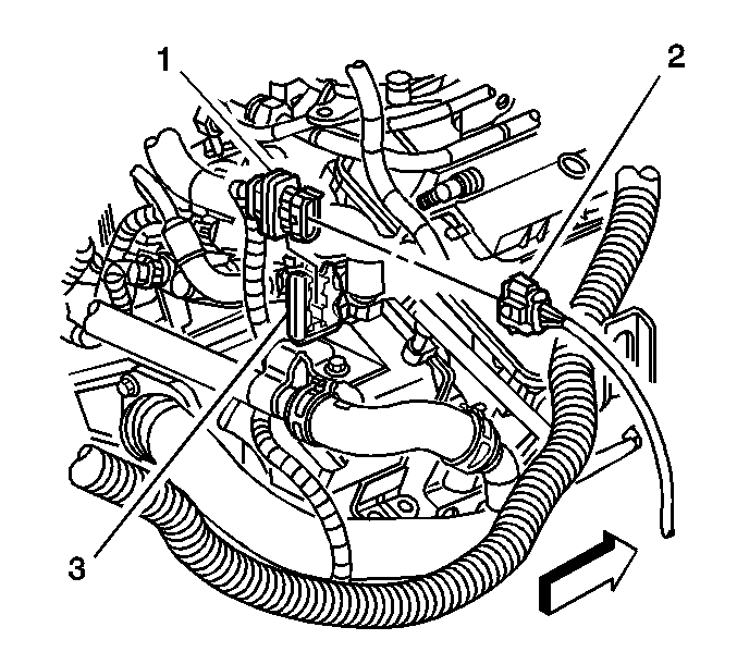
- Disconnect the vacuum brake booster hose (3) from the vacuum source.
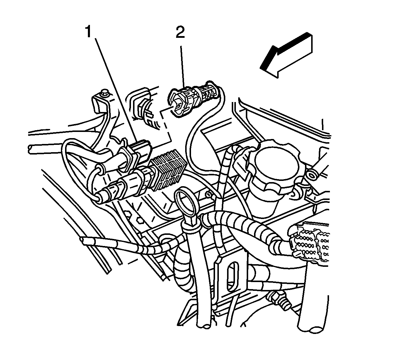
- Disconnect the left knock sensor electrical connector (2).
- Disconnect the camshaft position electrical connector.
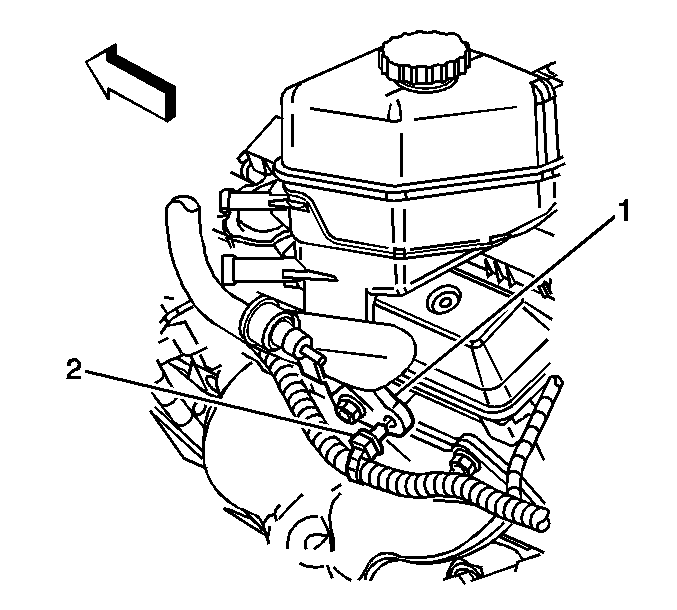
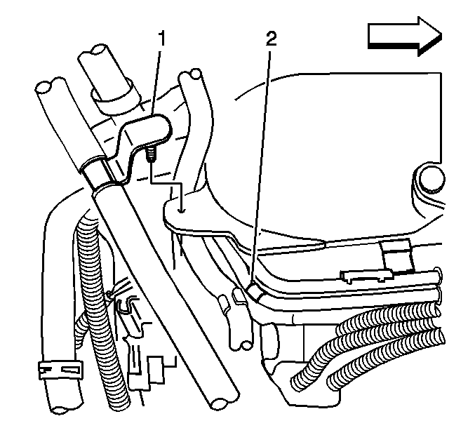
- Remove the wiring harness clip (2) from the power steering reservoir mounting bracket (1).
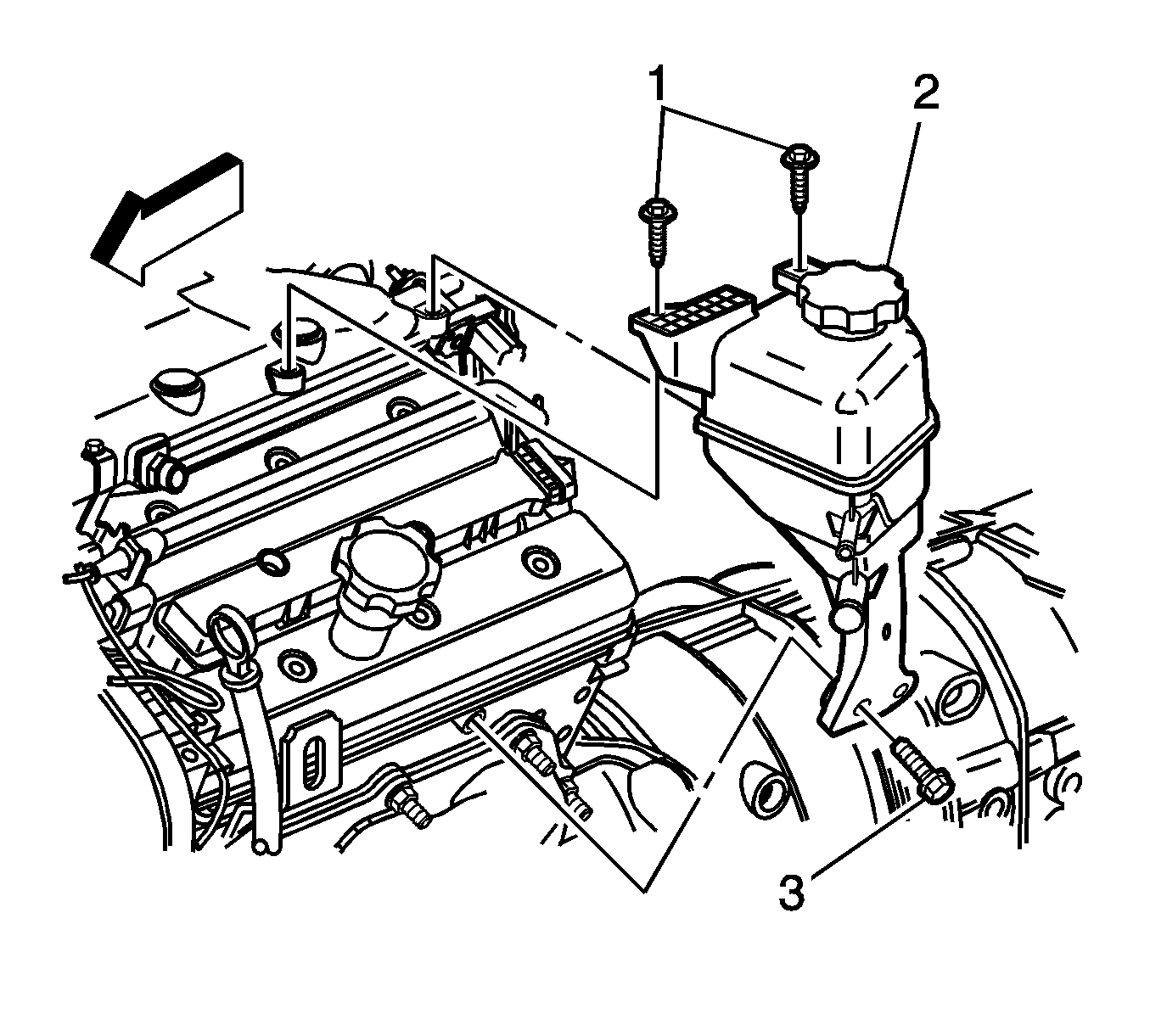
- Remove the remote power steering fluid reservoir (2) mounting bolts (1,3).
- Position the reservoir away from the cam cover assembly.
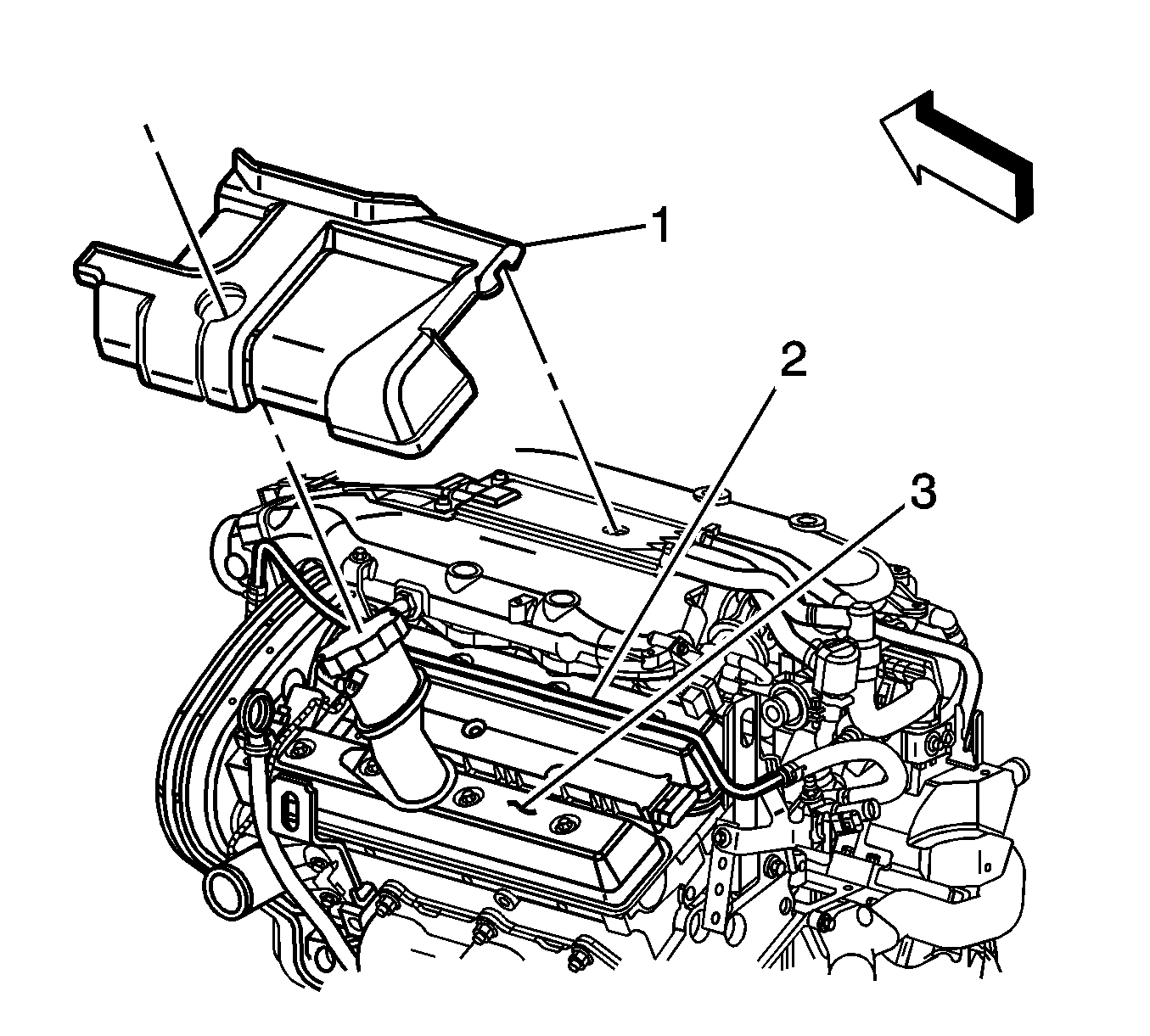
- Install the LH Manifold Cover Assembly (1), P/N 12578954, over the cam cover (3) and the throttle body heater inlet hose/pipe (2). Ensure the black plastic vacuum pipe and sensor leads do not become trapped under the cover.
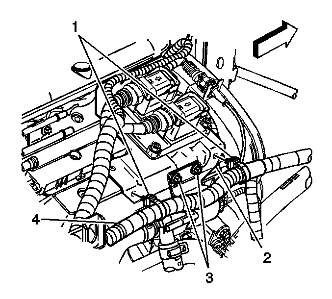
- Remove the 2 cable harness clips (1) securing the engine wiring harness (4) to the engine control module (ECM) bracket (2).
- Remove the 2 bolts (3) securing the afterboil coolant pump to the ECM bracket.
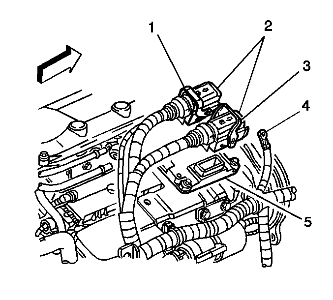
- Flip the release levers (1,3) to the open position and disconnect the ECM connectors (2) from the ECM (5).
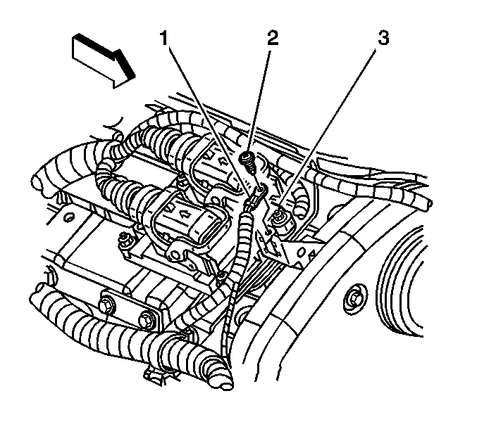
- Remove the screw (2) securing the ECM ground wire (1) to the ECM (3).
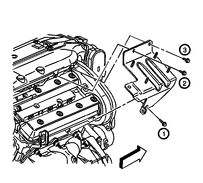
- Remove the ECM bracket bolts (2,3).
- Remove the bolt, located next to (1), that secures the coolant inlet pipe to the ECM bracket.
- Remove the ECM bracket bolt (1).
- Remove the ECM bracket from the engine with the ECM still attached.
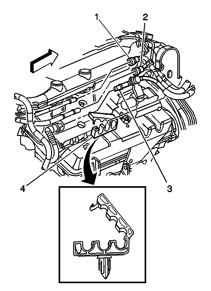
- Open the hose retainer clip (4) in order to remove the hose/pipes.
- Disconnect the fuel lines (1,2) from the fuel rail. Plug the open outlets to prevent fluid loss and contamination.
- Disconnect the evaporative emission (EVAP) quick connect fitting (3).
- Install the RH Manifold Cover Assembly (1), P/N 12548955.
- Disconnect the electrical connector (2) from the coil pack (1).
- Disconnect the heated oxygen sensor connector (2).
- Remove the connector (1) from the bracket (3).
- For Information Only: (1) is located ONLY on RHD vehicles.
- Disconnect the crankcase ventilation dirty air hose retainer (2) from the fuel pipe.
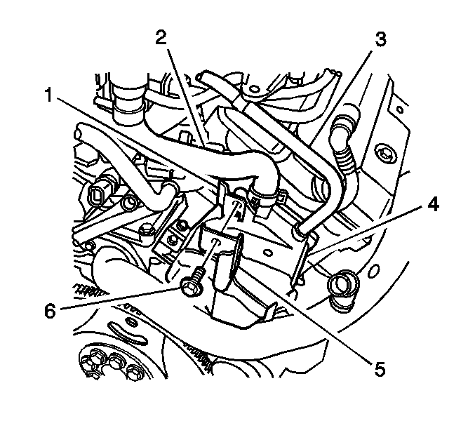
- Remove the bolt (6) that secures the heated oxygen sensor connector bracket (5) and the EVAP canister purge valve assembly bracket (1).
- Position the EVAP canister purge valve assembly rearward away from the engine.
- From the RH side of the engine, slide the Rear Manifold Cover Assembly (1), P/N 12578956, into position at the rear of the engine below the fuel pressure regulator.
- Align the EVAP canister purge valve assembly to the engine.
- Install the bolt (6) that secures the heated oxygen sensor connector bracket (5) and the EVAP canister purge valve assembly bracket (1).
- For Information Only: (1) is located ONLY on RHD vehicles.
- Connect the crankcase ventilation dirty air hose retainer (2) to the fuel pipe.
- Install the connector (1) to the bracket (3).
- Connect the heated oxygen sensor connector (2).
- Connect the electrical connector (2) to the coil pack (1).
- Connect the fuel lines (1,2) to the fuel rail.
- Connect the evaporative emission (EVAP) quick connect fitting (3).
- Position the hose/pipes in the hose retainer clip (4) and close.
- Position the ECM and bracket to the engine and install the retaining bolts.
- Install the bolt , located next to (1), that secures the coolant inlet pipe to the ECM bracket.
- Install the 2 bolts (3) that secure the afterboil coolant pump to the ECM bracket.
- Install the 2 cable harness clips (1) that secure the engine wiring (4) to the ECM bracket (2).
- Install the screw (2) that secures the ECM ground wire (1) to the ECM (3).
- Carefully align the ECM connectors (2) and connect to the ECM (5).
- Flip the release levers (1,3) to the closed position.
- Install the remote power steering fluid reservoir (2) mounting bolts.
- Install the wiring harness clip (2) to the power steering reservoir mounting bracket (1).
- Connect the camshaft position electrical connector.
- Connect the left knock sensor electrical connector (2).
- Connect the vacuum brake booster hose (3) to the vacuum source.
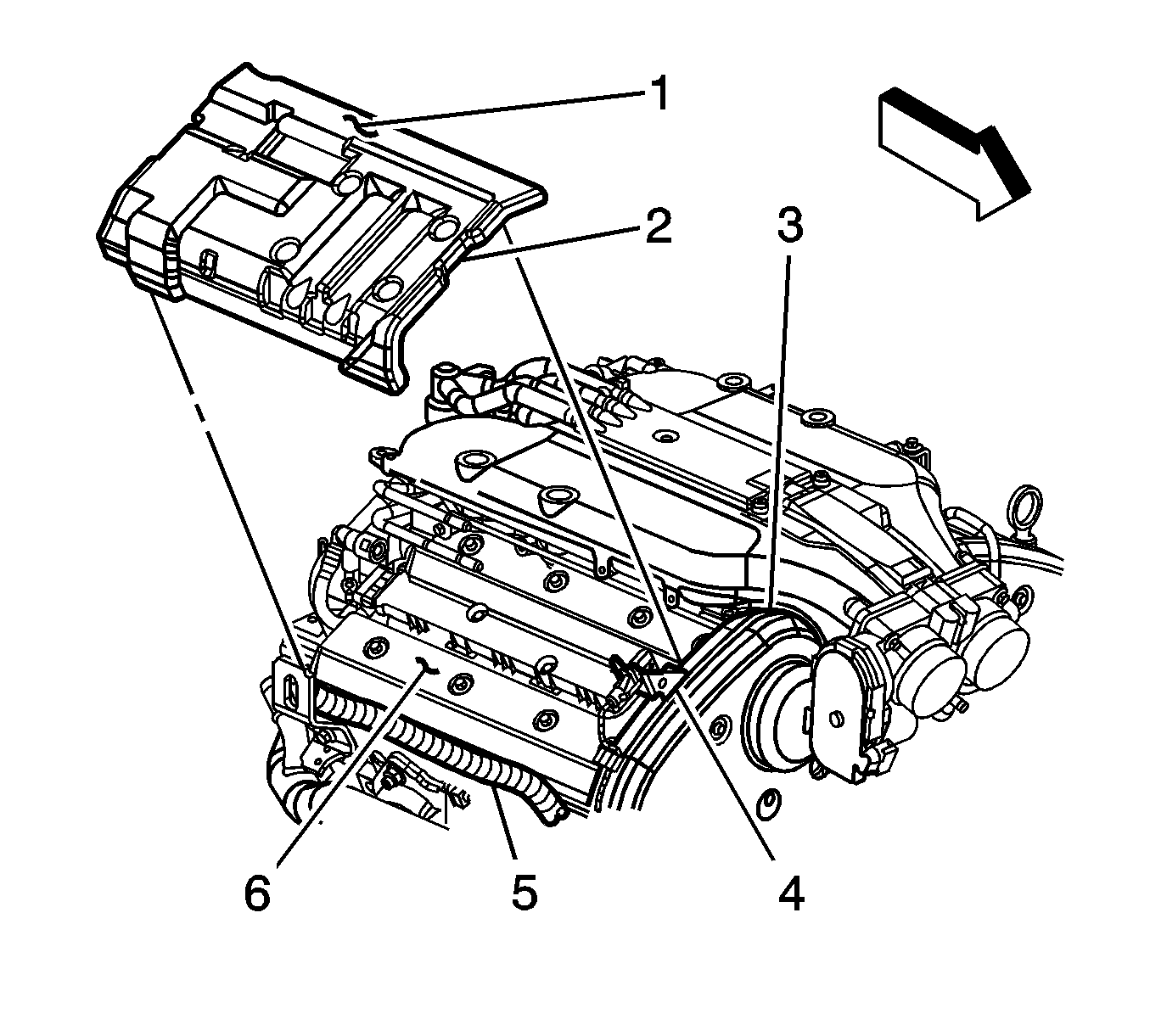
| 21.1. | Insert the right hand side of the cover between the engine wiring harness (5) and the cam cover (6). |
| 21.2. | Align the cover's front notch (2) with the right knock sensor bracket (4). |
| 21.3. | Ensure the cover is against the engine rear timing belt cover (3). |
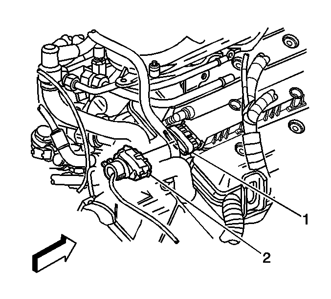
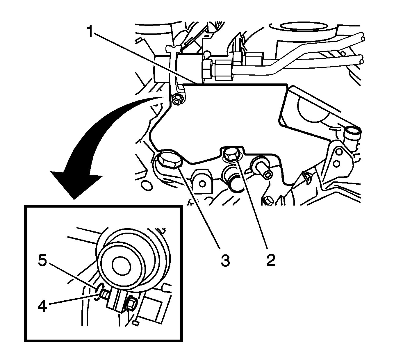
| 29.1. | Align the hole (5) in the cover with the fuel pressure regulator clamp bolt (4). |
| 29.2. | Align the notches in the bottom portion of the cover with the crossover pipe plug (2) and the water crossover fitting (3). |


Tighten
Tighten the ECM bracket to cylinder head bolt (1) to 20 N·m(15 lb in).
Tighten the ECM bracket to intake plenum bolts (2,3) to 8 N·m(71 lb in).
Tighten
Tighten the coolant inlet pipe bolt to 20 N·m(15 lb in).

Tighten
Tighten the afterboil coolant pump bolts to 10 N·m(89 lb in).

Tighten
Tighten the ECM ground wire screw to 4.5 N·m(40 lb in).


Tighten
Tighten the reservoir to intake plenum bolts (1) to 9 N·m(80 lb in).
Tighten the reservoir to cylinder head bolt (3) to 25 N·m(18 lb in).


Parts Information
Part Number | Description |
|---|---|
12578954 | Cover Asm -- Intake Manifold, LH |
12578955 | Cover Asm -- Intake Manifold, RH |
12578956 | Cover Asm -- Intake Manifold, Rear |
Parts are currently available from GMSPO.
Warranty Information
For vehicles repaired under warranty, use:
Labor Operation | Description | Labor Time |
|---|---|---|
J1953* | Covers, Engine Noise -- Install | 1.1 hrs |
*This is a new labor operation to be used only with this bulletin. It will not be published in the Labor Time Guide. | ||
