Noise, WindNoise, Flutter at Approximately 40 mph (64 km/h) (Diagnose and Replace Transmission as Required)

| Subject: | Noise, Wind Noise, Flutter at Approximately 40 mph (64 km/h) (Diagnose and Replace Transmission as Required) |
| Models: | 2003 Cadillac CTS |
| Built Prior to VIN Breakpoint 30132407 with 5 Speed Manual Transmission |
This bulletin is being revised to add service procedures and parts and warranty information. Please discard Corporate Bulletin Number 02-007-29-006 (Section 07--Transmission/Transaxle).
Condition
Some customers may comment that a fluttering or wind noise is heard while driving in 5th gear above approximately 40 mph (64 km/h). The noise is not present in 4th gear under the same type of driving conditions.
Cause
When the transmission is in 5th gear, normal engine harmonics cause the 4th gear synchronizer assembly to vibrate, creating the noise.
Diagnosis
This procedure is not intended to correct other noises that are a characteristic of the M35 transmission (for example: gear whine or neutral gear rattle).
Verify the customer's concern by driving the vehicle at 40-45 mph (64-72 km/h) in 5th gear. When the noise is heard, shift into 4th gear while maintaining vehicle speed. It may take several attempts to hear this noise as it is not a loud noise. You may need the customer to be present. If the noise is no longer present, the concern is the 4th gear synchronizer rattle in 5th gear.
Correction
Replace the transmission.
Place the vehicle in position to be raised on a hoist.
Tools Required:
J 42640 Steering Column Anti-Rotation Pin
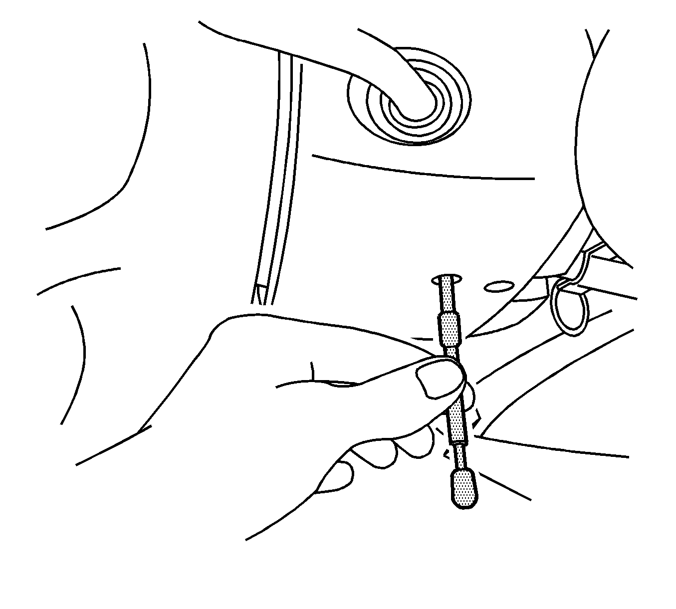
Notice: The front wheels of the vehicle must be maintained in the straight ahead position and the steering column must be in the LOCK position before disconnecting the steering column or intermediate shaft. Failure to follow these procedures will cause improper alignment of some components during installation and result in damage to the SIR coil assembly.
- Turn the steering wheel so that the front wheels are pointing straight ahead.
- Turn the ignition lock cylinder to the lock position and remove the key.
- Insert the steering column anti-rotation pin, J 42640 through the access hole in the lower steering column trim cover.
- Raise and properly support the vehicle in accordance with the guidelines in Service Information (SI) Document # 813128.
- Remove the two bolts securing the floor panel tunnel brace to the floor panel and remove the brace from the vehicle.
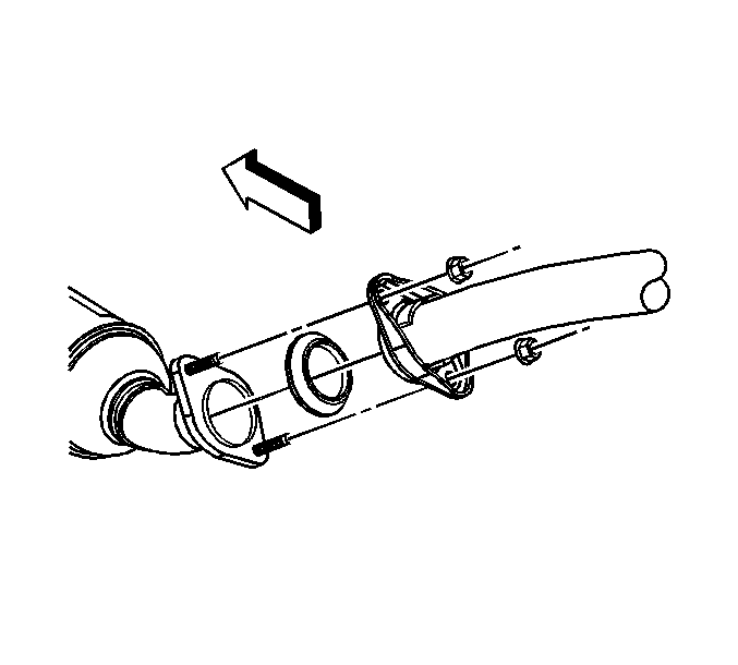
- With a jack stand supporting the exhaust system, remove the nuts and bolts, two (2) per side, securing the catalytic converters to the exhaust pipe assembly.
- Slide the exhaust hangers free from the support rods and remove the exhaust system from the vehicle.
- Disconnect the wire connectors for the oxygen sensors at the catalytic converter hanger bracket.
- Remove the retainer (nuts), three (3) per side, retaining the catalytic converters to the exhaust manifold.
- Remove the nuts securing the catalytic converters to the catalytic converter hanger bracket, two (2) per side.
- Remove the catalytic converter from the vehicle.
- Depress the retainer which retains the oxygen sensor connectors to the catalytic converter bracket and let the wires hang.
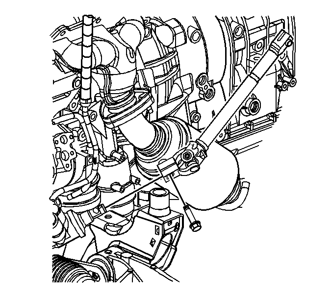
- Remove the two (2) bolts securing the catalytic converter hanger bracket to the transmission and remove the bracket.
- Remove the three (3) propeller shaft coupler to transmission flange bolts and nuts (1).
- Slide the propeller shaft rearward slightly to clear the transmission output shaft flange and support the propeller shaft to the underside of the vehicle with mechanic's wire.
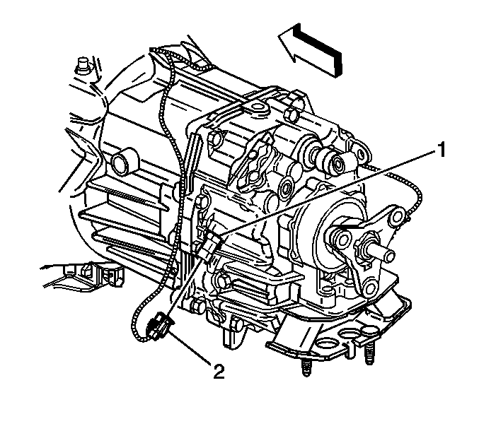
- Disconnect the vehicle speed sensor wire from the electrical connector.
- Disconnect the backup lamp electrical connector (2) from the backup lamp switch (1).
- Remove the clutch hydraulic hose retaining clip (1) from the clutch slave cylinder.
- Disconnect the clutch hydraulic hose (2) from the clutch slave cylinder.
- Remove the transmission mount lower mounting nuts.
- Support and secure the transmission with a suitable transmission jack.
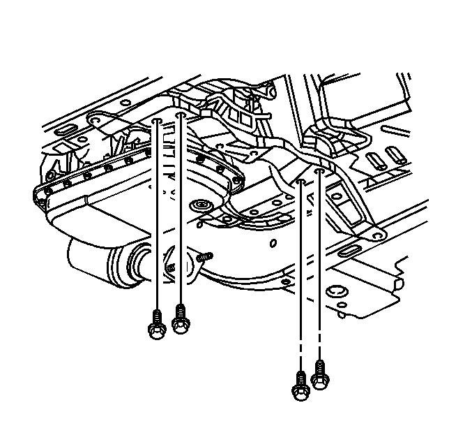
- Remove the rear transmission support outer bolts.
- Remove the four (4) inner transmission mounting bolts and remove the support from the vehicle.
- Remove the steering gear intermediate shaft retaining bolt and disconnect the shaft from the steering gear.
- Position a jack stand with a 4X4 on top under the rear engine frame to support the engine and transmission assembly.
- Loosen the front frame bolts about three (3) turns. (Do not remove the front bolts).
- Remove the rear frame bolts.
- Lower the transmission jack and the jack stand to obtain about 38 mm (1.5 in) clearance between the rear frame mount and the body of the vehicle.
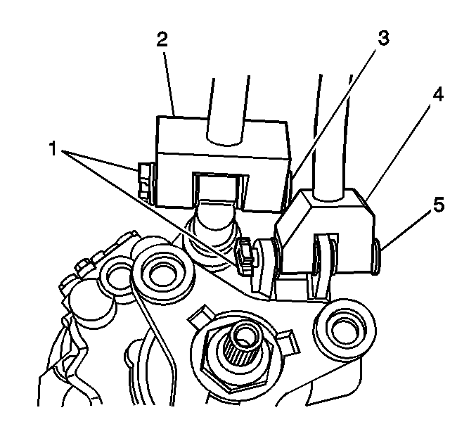
- Remove the shift control rod pin and reaction arm pin retaining clips (1) from both shift levers.
- Remove the shift control rod pin (3), the reaction rod pin (5), and disconnect the rods from the transmission.
- Disconnect the wiring harness retainers from the transmission mounting bolts.
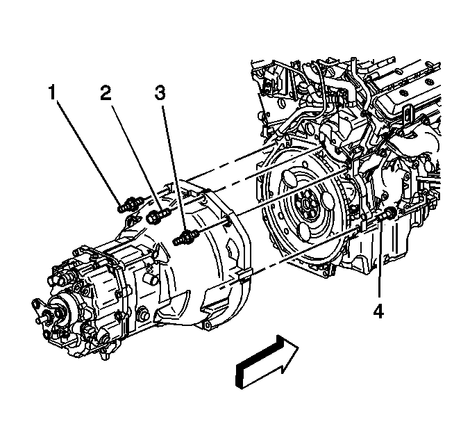
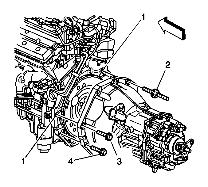
- Remove the transmission mounting bolts (1-4)
- Remove transmission mounting bolts (3, 4).
- Lower the transmission jack while removing the transmission from the vehicle.
- With the new transmission on the transmission jack, carefully raise the transmission into position.
- Loosely install all transmission to engine mounting bolts. When all transmission to engine bolts have been installed into position and the interface of the transmission bell housing and rear engine face are properly seated, tighten the bolts in the following sequence.
- Tighten the transmission mounting bolts (2-3) to 75 N·m(55 lb ft).
- Tighten the transmission mounting bolt (4) to 50 N·m(37 lb ft).
- Tighten the remaining transmission mounting bolts to 75 N·m(55 lb ft).
- Reconnect the engine wiring harness retaining clips to the transmission mounting bolts.
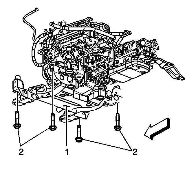
- Raise the engine and transmission assembly and engine frame into proper position with the jack stand and transmission jack.
- Install the rear frame mounting bolts # 2.
- Remove the jack stand and wood block supporting the rear frame.
- Connect the intermediate shaft to the steering gear.
- Install the intermediate shaft retaining bolt.
- Position the shift control rods and install the pins and retaining clips.
- Position the rear transmission support mount into place on the transmission and loosely install the center support retainers. DO NOT tighten at this time.
- Route the clutch hydraulic hose and wiring harness for the VSS and backup lamp wiring into position.
- Raise the transmission jack so the transmission rear mount support is positioned into place.
- Install the two (2) outer transmission support mounting bolts. DO NOT tighten at this time.
- Install the four (4) inner transmission mounting bolts. DO NOT tighten at this time.
- Tighten the two (2) transmission support outer bolts to 60 N·m(44 lb ft).
- Tighten the four (4) transmission inner support to body bolts to 60 N·m(44 lb ft).
- Tighten the two (2) transmission lower mounting nuts to 60 N·m(44 lb ft).
- Install the clutch hydraulic hose retaining clip (1) to the clutch slave cylinder.
- Align the clutch hydraulic hose locating tab with the notch in the slave cylinder hose fitting and push the hose (2) into the slave cylinder until a "click" is heard.
- Tug gently on the hose to see that it is properly retained into position.
- Reconnect the wiring to the VSS and back-up lamp switches.
- Install the propeller shaft coupler to flange bolts.
- Insert the catalytic converter hanger bolts into the converter hanger and properly position in place.
- Replace the crush type seal, P/N 25731281, from the catalytic converter to exhaust manifold interface, both sides.
- Place the catalytic converter into position over the bracket studs and loosely install the two (2) retaining nuts.
- Align the converter to the exhaust manifold and install the three (3) retainers.
- Tighten the converter to manifold retainers to 22N·m(16 lb ft).
- Tighten the catalytic converter hanger retainers to 25N·m(18 lb ft).
- Place a jack stand under the vehicle in position to support the exhaust system, at the front muffler location.
- With the aid of an assistant, place the exhaust system into position and slide the hangers over the brackets at the rear of the vehicle.
- Align the left side exhaust pipe to the catalytic converter; place a new seal, P/N 25709703, into position and loosely install the retainers. DO NOT TIGHTEN.
- Align the right side exhaust pipe to the catalytic converter; place a new gasket, P/N 25736235, into position and loosely install the retainers. DO NOT TIGHTEN.
- Shake the exhaust system slightly to ensure proper alignment. Raise/lower the jack stand as required to achieve proper alignment of the exhaust system.
- Remove the jack stand.
- Reinstall the floor panel tunnel brace.
- Check and adjust the transmission fluid level, if required.
- Lower the vehicle.
- Remove the steering column anti-rotation pin, J 42640.
- Road test the vehicle for proper operation of the transmission in all forward and reverse gears.
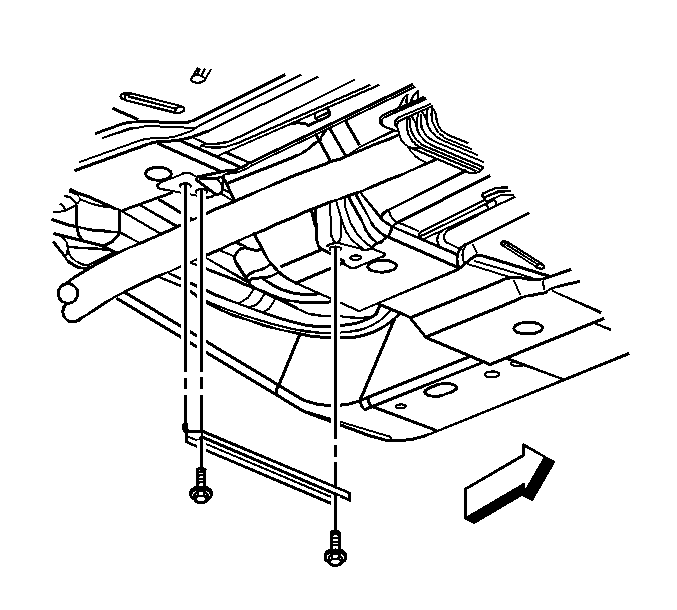
Notice: Do not remove the exhaust system as an assembly. The exhaust system must be separated from the exit end of the catalytic converters. Disconnecting the catalytic converter at the manifold and removing the complete exhaust system as an assembly will damage the flex joint and require replacement of the exhaust system from the catalytic converter back (not covered by the warranty).
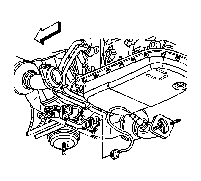
Notice: Due to the extremely close clearances, it is recommended that the catalytic converters be removed. Damaged oxygen sensors which result from replacing the transmission improperly without removal of the catalytic converters will not be covered under warranty.
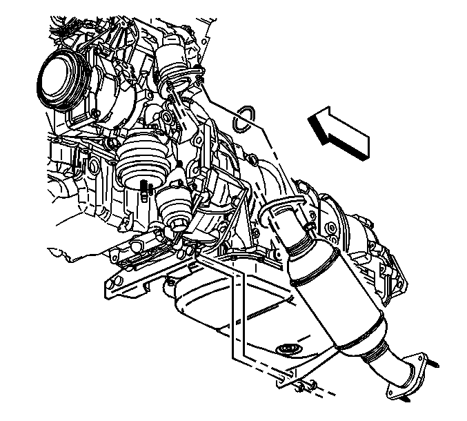
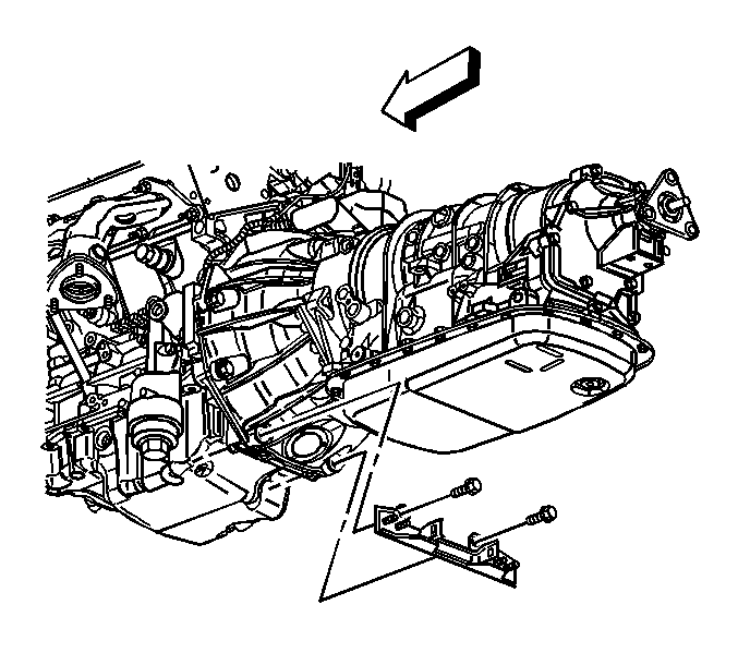
Important: Remove only the propeller shaft coupler to transmission flange bolts, the bolts with the nuts on the engine side of the flange. DO NOT remove the coupler from the propeller shaft, the bolts with the nut on the propshaft side of the flange.
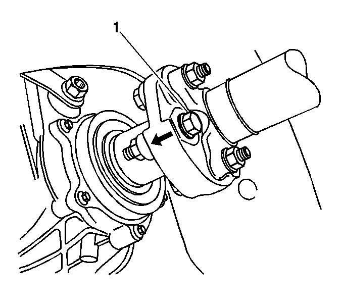
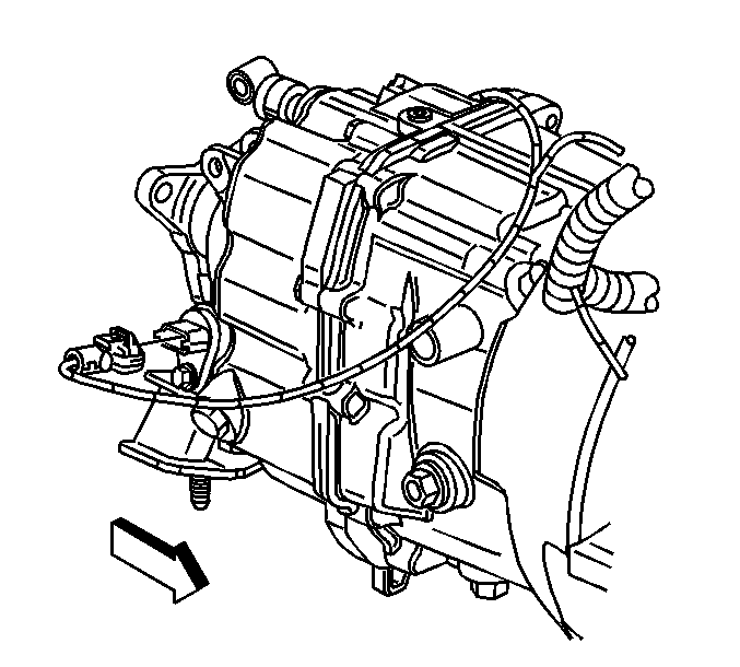
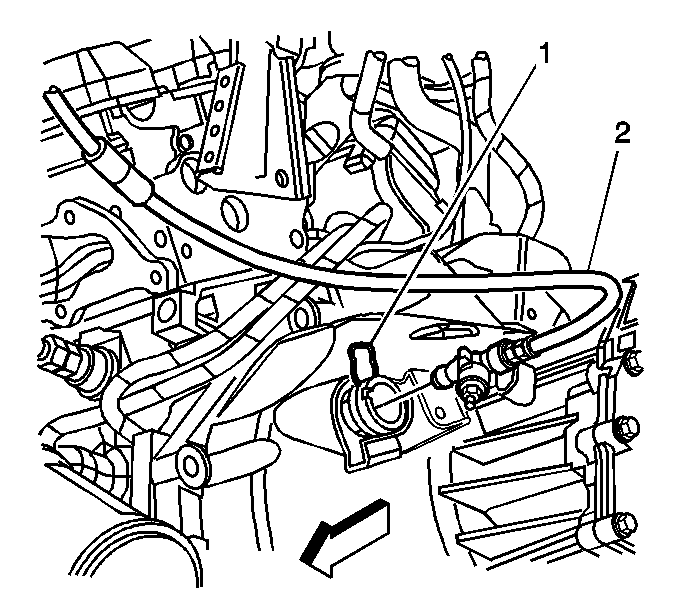
Important: It is not necessary to plug the lower hose end or slave cylinder fitting as they are equipped with check valves. Only minimal fluid loss may be experienced.
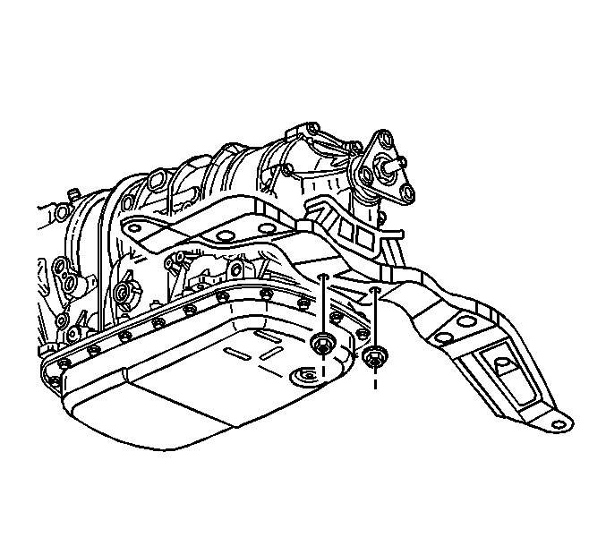
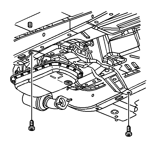
Important: Locate the three (3) propshaft retaining nuts and bolts. Clean them thoroughly with denatured alcohol, or equivalent, of all thread locking residue and contaminants. Apply threadlocker, P/N 12345493 (Canadian P/N 10953488), or equivalent, to the bolts. Ensure there are no gaps in the threadlocker along the length of the filled area of the bolt. Allow to cure for approximately ten minutes prior to usage.
Notice: Ensure the transmission input shaft splines are properly aligned with the splines on the clutch disc and that the bell housing is properly positioned over the dowel pins and seated to the rear engine face before installing any bolts. If the bolts are used to pull the transmission into position, the pressure plate, clutch disc, and/or transmission input shaft pilot bearing may be damaged.

Tighten
Tighten
Tighten all four (4) frame mounting bolts # 2 to 191 N·m(141 lb ft).

Tighten
Tighten the intermediate shaft retaining bolt to 48 N·m(35 lb ft).

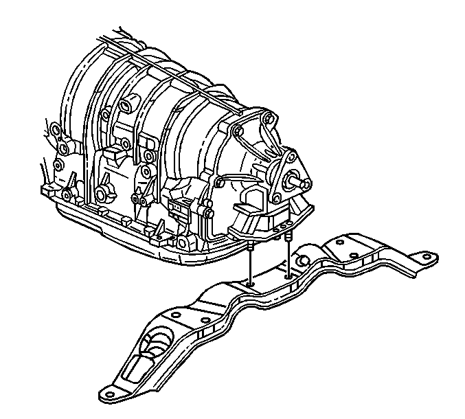


Tighten the transmission support mounting bolts in the following sequence:
Important: Ensure the clutch hydraulic hose is routed in an upward direction above the clutch slave cylinder with no sharp bends, kinks, or downward loops. Ensure the clutch hydraulic hose does not come in contact with any sharp or potentially hot surfaces.


Tighten
Tighten the propeller shaft coupler to transmission flange bolts to
85 N·m (63 lb ft).

Tighten
Tighten the converter hanger to transmission bolts to 50 N·m (37 lb ft).

Tighten

Tighten
Tighten the catalytic converter nuts to 15 N·m (11
lb ft), both sides.

Tighten
Tighten the floor panel tunnel brace bolts to 25 N·m (18 lb ft).
Parts Information
Part Number | Description | Qty |
|---|---|---|
12579386 | Transmission, Manual 5 Speed | 1 |
25731281 | Gasket | 2 |
25709703 | Seal, Exhaust | 1 |
25736235 | Gasket, Exhaust | 1 |
Parts are currently available from GMSPO.
Warranty Information
For vehicles repaired under warranty, use:
Labor Operation | Description | Labor Time |
|---|---|---|
K2720 | Transmission Assembly-Replace | 2.9 hrs |
