Tools Required
| • | J 8059 Snap Ring Pliers |
| • | J 41048 Drive Axle Swage Ring Clamp |
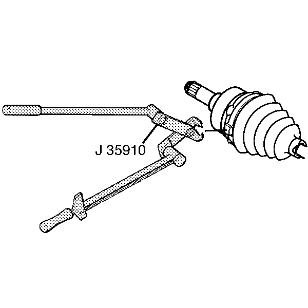
| • | J 35910 Drive Axle Seal Clamp Pliers |
Removal Procedure
- Remove the halfshaft from the vehicle. Refer to Wheel Drive Shaft Replacement .
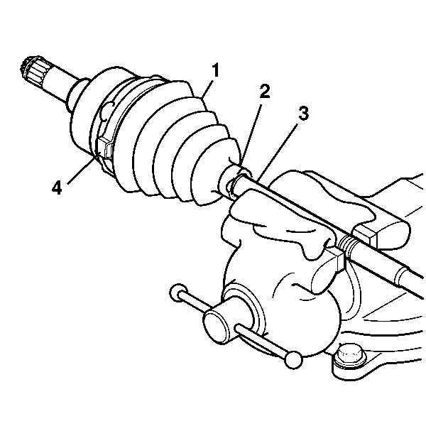
- Wrap a towel around the halfshaft bar (3) and clamp horizontally in a vise.
- Cut large boot retaining clamp (4) from boot (1) with a pair of side cutters. Discard the retaining clamp.
- Use a hand grinder to cut through the halfshaft bar swage ring (2).
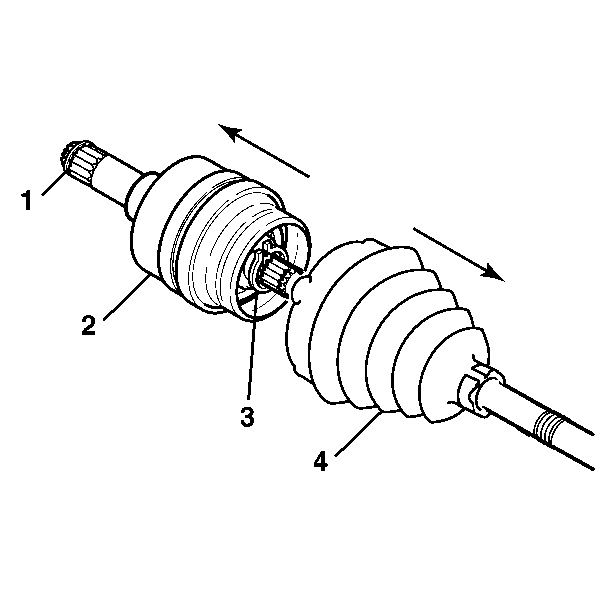
- Slide the boot (4) along the halfshaft bar away from the cross groove joint (2) and wipe away any grease from the face of the cross groove joint assembly.
- Spread the ears of the cross groove joints race retaining ring (3) using J 8059 . Discard the retaining ring.
- Remove the cross groove joint assembly (2) from the halfshaft bar.
- Remove the transmission retaining ring (1) from the cross groove joint assembly using J 8059 . Discard the transmission retaining ring (1).
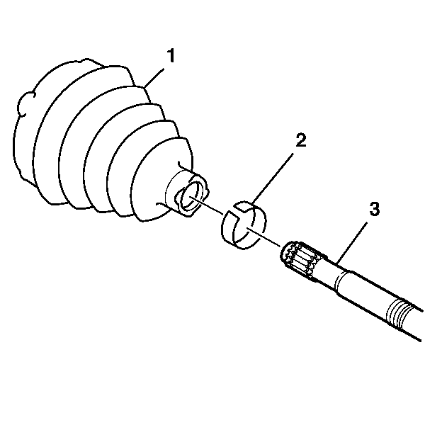
- Remove the inner boot (1) and the swage ring (2) from the halfshaft bar (3). Discard the boot and swage ring.
- Use a parts brush and solvent to carefully clean, flush, and drain the joint. Allow the components to completely dry.
- Use a wire brush to remove any rust in the boot mounting grooves on the halfshaft bar and the cross groove joint boot adapter.
- Inspect the cross groove joint assembly for visible damage or wear. Replace the cross groove joint assembly if necessary.
Important: The cross groove joint shank must be parallel to the halfshaft bar prior to its removal. Never allow the inner race or cage to rotate within the outer race when the cross groove joint is separated from the halfshaft bar.
The cross groove joint design uses precision machining and selected dimensional component fits to achieve proper assembly and operation. Due to its complexity, it should not be disassembled during service.Keep the cross groove joint's inner race and cage straight and level relative to the outer race, push the inner race and cage to the bottom of the outer race bore to displace the grease.
Installation Procedure
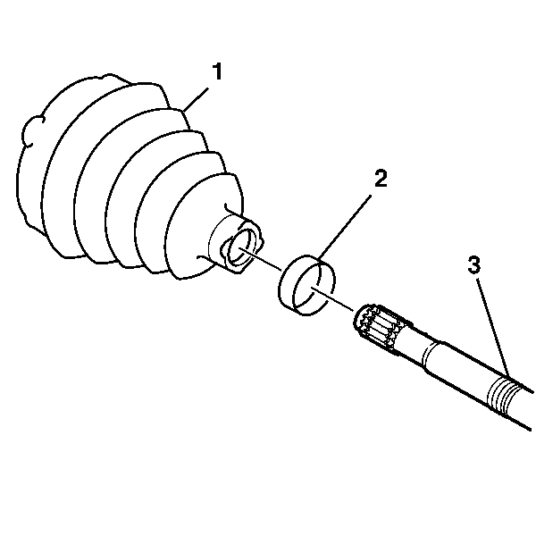
- Install the new swage ring (2) on the neck of the new inner boot (1). Do not swage.
- Slide the inner boot onto the halfshaft bar and position the neck of the inner boot into the boot groove (3) on the halfshaft bar. The largest groove below the sight groove on the halfshaft bar is the boot groove.
- Position the inboard end of the halfshaft assembly (1) using J 41048 .
- The swage ring is swaged using J 41048 by the following method:
- Insert the bolts and tighten by hand until snug.
- Loosen the bolts.
- Install the new race retaining ring (2) into the inner race using J 8059 .
- With the cross groove joint inner race and cage still at the bottom of the outer race bore, pack half of the provided grease into the cross groove joint assembly (1) and use the remainder to fill the inner boot (3).
- Place the new large clamp (4) over the large end of the inner boot (3).
- Install the new transmission retaining ring (5) onto the cross groove joint assembly (1) using J 8059 .
- Push the cross groove joint assembly (1) onto the halfshaft bar until the retaining ring (2) seats itself in the appropriate groove on the halfshaft bar.
- Stroke the joint to dimension A of 271 mm (10.7 in).
- Crimp the large boot retaining clamp using J 35910 with a breaker bar and torque wrench.
- Torque until the proper gap dimension of 1.9 mm (0.075 in) is reached.
- Fully stroke the cross groove joint several times to disperse grease throughout the joint.
- Install the halfshaft to the vehicle. Refer to Wheel Drive Shaft Replacement .
Notice: Do not cut through the wheel drive shaft inboard or outboard boot during service. Cutting through the boot may damage the sealing surface of the housing and the tripot or the constant velocity joint bushing. Damage to the sealing surface may lead to water and dirt intrusion and premature wear of the constant velocity joint.
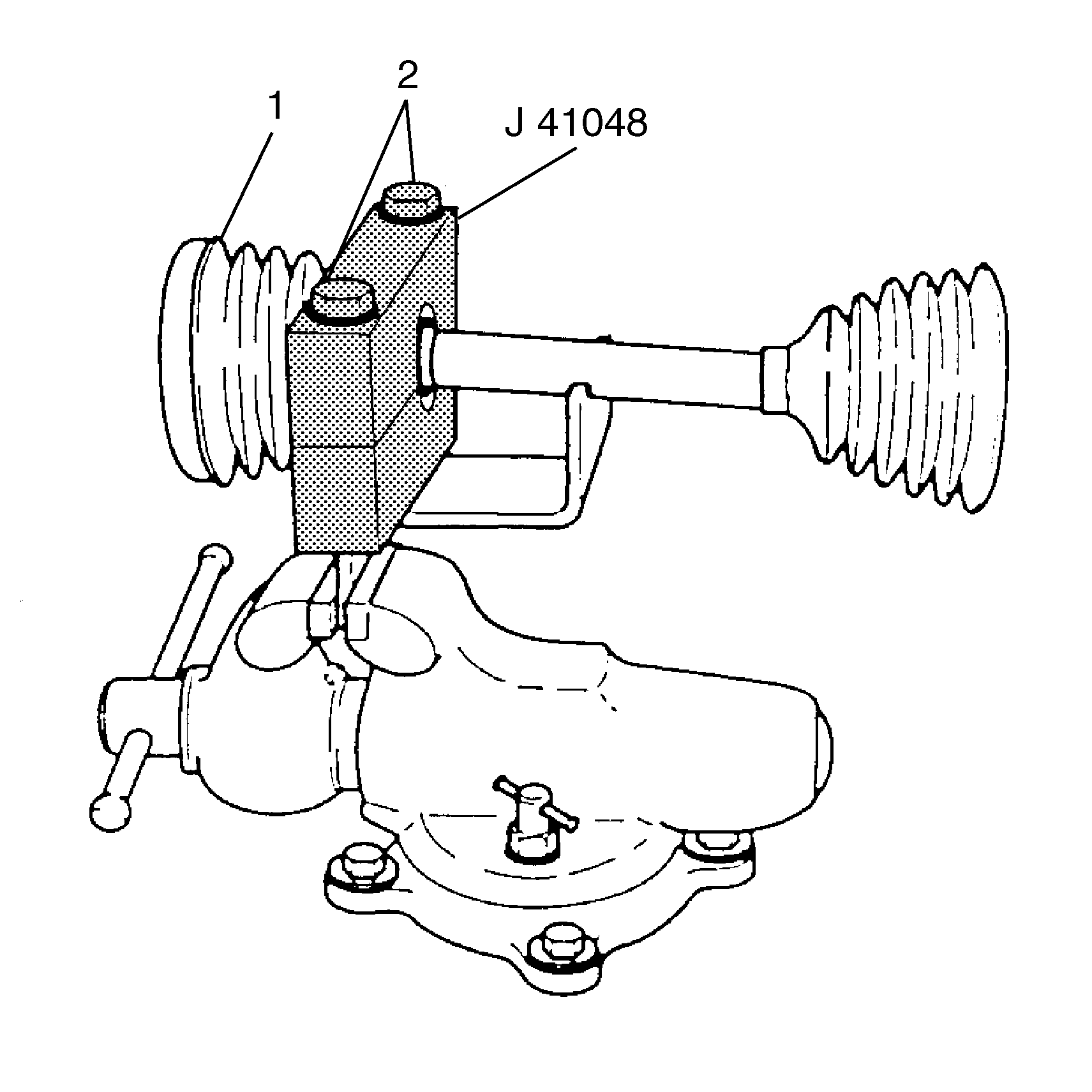
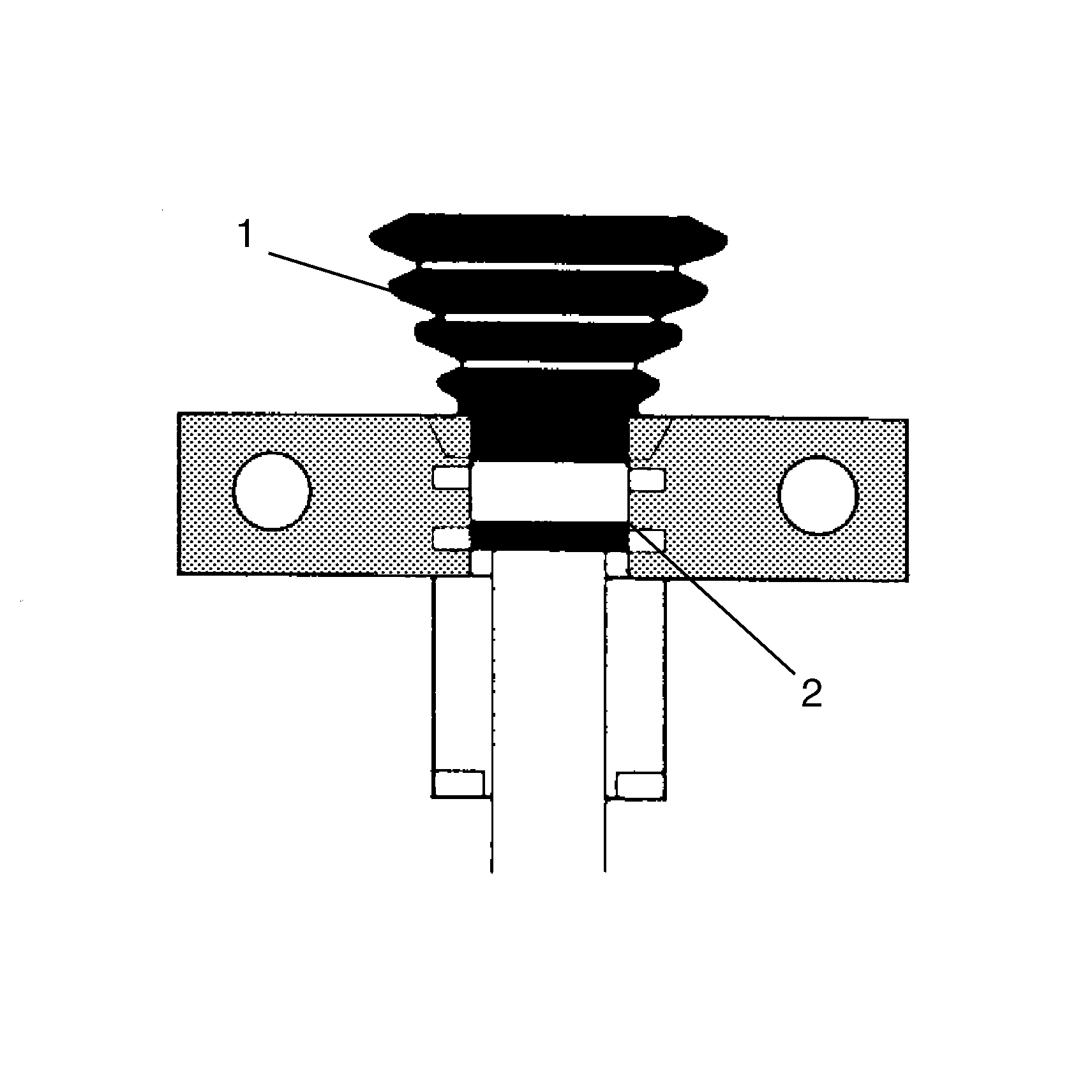
| 4.1. | Position the inner end of the halfshaft assembly in J 41048 . |
| 4.2. | Align the swage ring (2) with the boot (1). |
Notice: Refer to Fastener Notice in the Preface section.
Tighten
Tighten each bolt 180 degrees at a time using a ratchet wrench. Alternate between each bolt until both sides are bottomed.
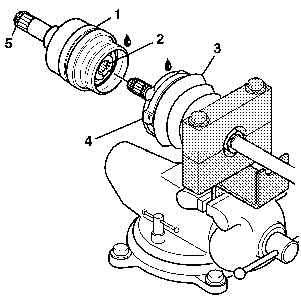
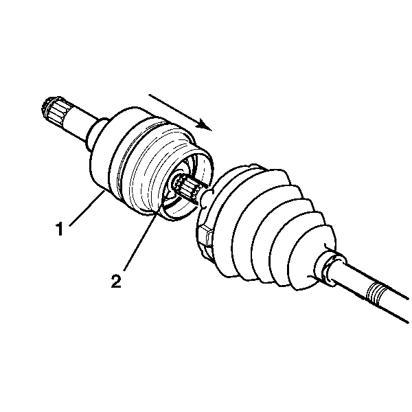
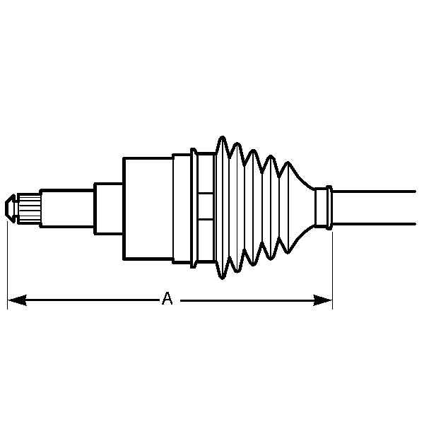
Important: The inner boot must not be dimpled, stretched, or out of shape in any way. If necessary, equalize the air pressure in the inner boot and shape properly by hand.
Tighten
Tighten to 176 N·m (130 lb ft).
