|
| ||||||||||||||
|---|---|---|---|---|---|---|---|---|---|---|---|---|---|---|---|
Connector Part Information |
| Connector Part Information |
| ||||||||||||
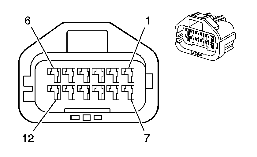
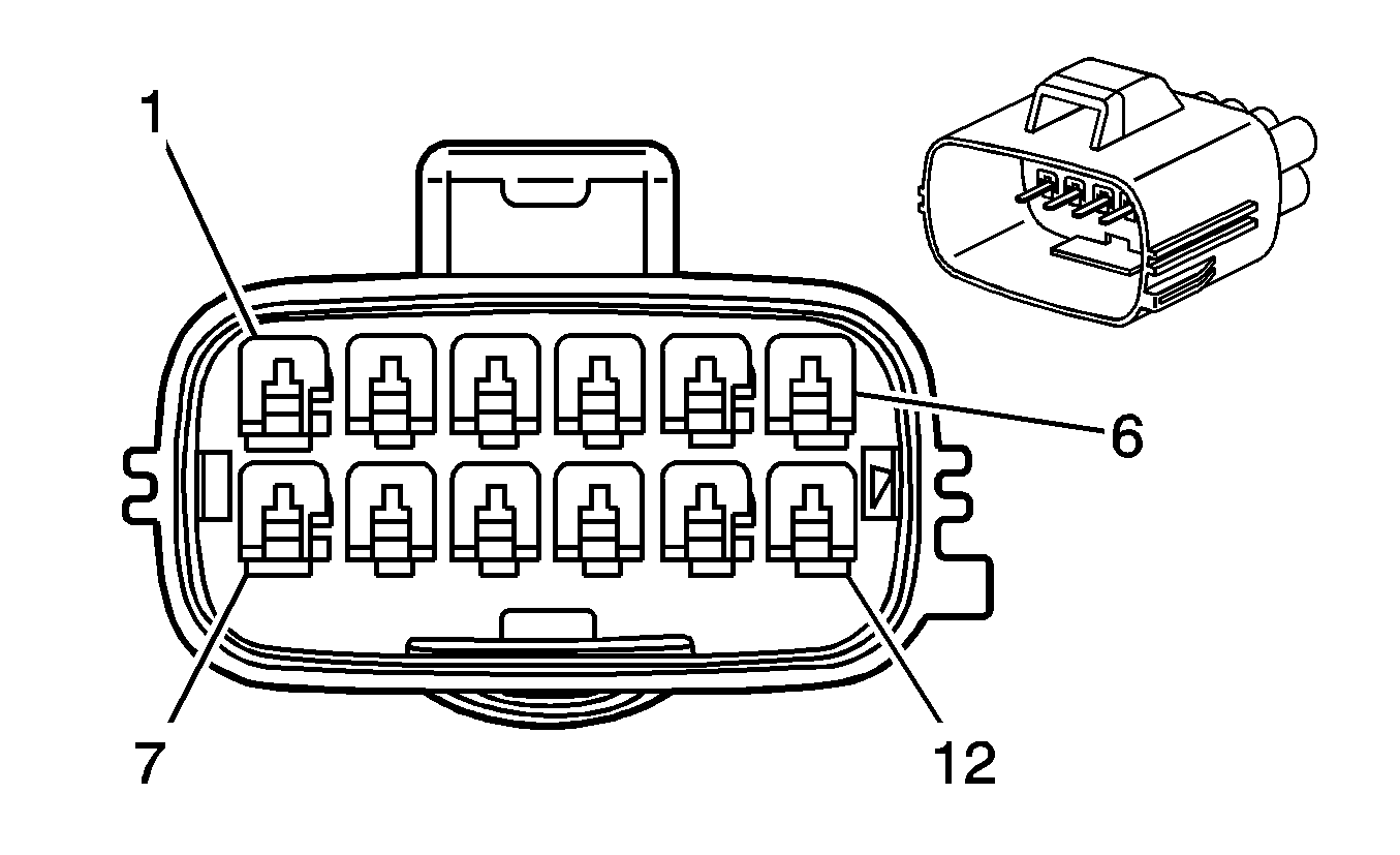
Pin | Wire Color | Circuit No. | Function | Pin | Wire Color | Circuit No. | Function | ||||||||
1 | TN | 884 | Left Rear Wheel Speed Sensor Signal | 1 | TN | 884 | Left Rear Wheel Speed Sensor Signal | ||||||||
2 | OG | 885 | Left Rear Wheel Speed Sensor Low Reference | 2 | OG | 885 | Left Rear Wheel Speed Sensor Low Reference | ||||||||
3 | BN | 882 | Right Rear Wheel Speed Sensor Signal | 3 | BN | 882 | Right Rear Wheel Speed Sensor Signal | ||||||||
4 | WH | 883 | Right Rear Wheel Speed Sensor Low Reference | 4 | WH | 883 | Right Rear Wheel Speed Sensor Low Reference | ||||||||
5 | PK | 39 | Ignition 1 Voltage | 5 | PK | 39 | Ignition 1 Voltage | ||||||||
6 | D-GN/WH | 465 | Fuel Pump Relay Control | 6 | D-GN/WH | 465 | Fuel Pump Relay Control | ||||||||
7 | TN | 452 | Low Reference | 7 | TN | 452 | Low Reference | ||||||||
8 | D-GN | 890 | Fuel Tank Pressure Sensor Signal | 8 | D-GN | 890 | Fuel Tank Pressure Sensor Signal | ||||||||
9 | GY | 596 | 5-Volt Reference (LP1/LY7/LS6) | 9 | GY | 596 | 5-Volt Reference | ||||||||
10 | WH | 1310 | EVAP Canister Vent Solenoid Control | 10 | WH | 1310 | EVAP Canister Vent Solenoid Control | ||||||||
11 | D-BU | 1936 | Fuel Level Sensor Signal - Primary | 11 | D-BU | 1936 | Fuel Level Sensor Signal - Primary | ||||||||
12 | L-BU | 1937 | Fuel Level Sensor Signal - Secondary | 12 | L-BU | 1937 | Fuel Level Sensor Signal - Secondary | ||||||||
|
| ||||||||||||||
|---|---|---|---|---|---|---|---|---|---|---|---|---|---|---|---|
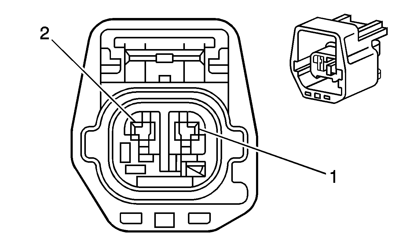
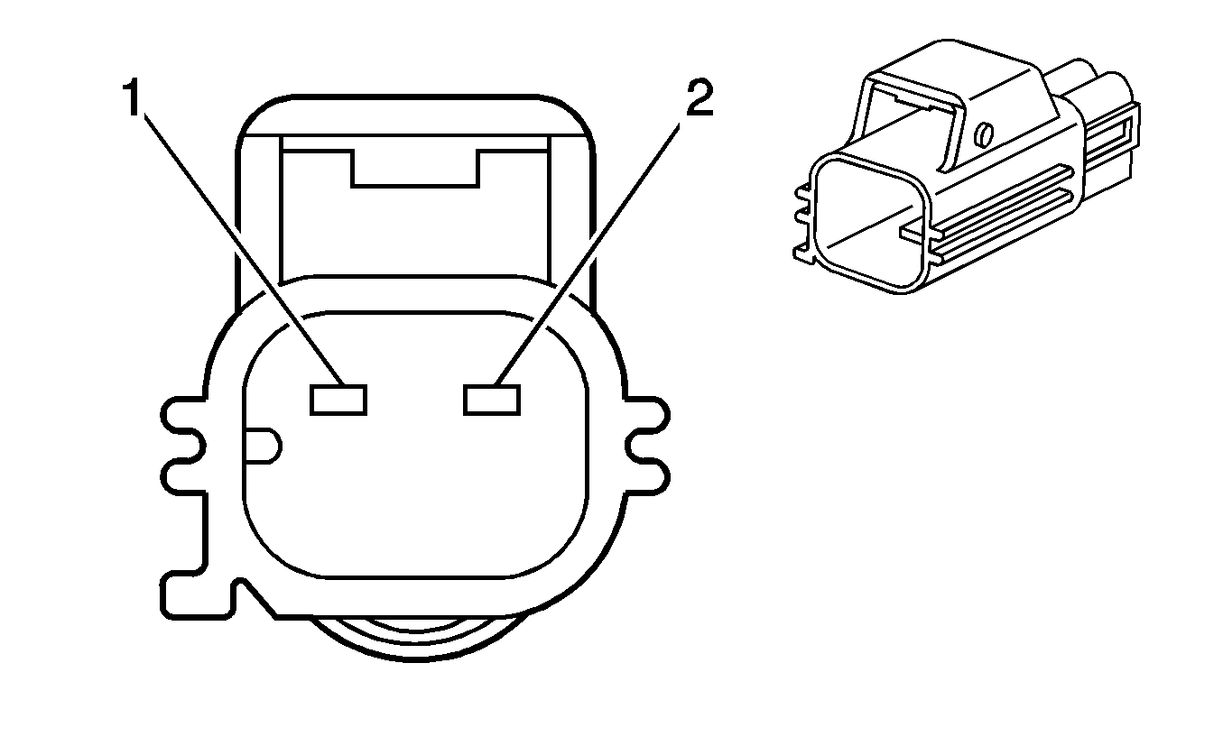
Connector Part Information |
| Connector Part Information |
| ||||||||||||
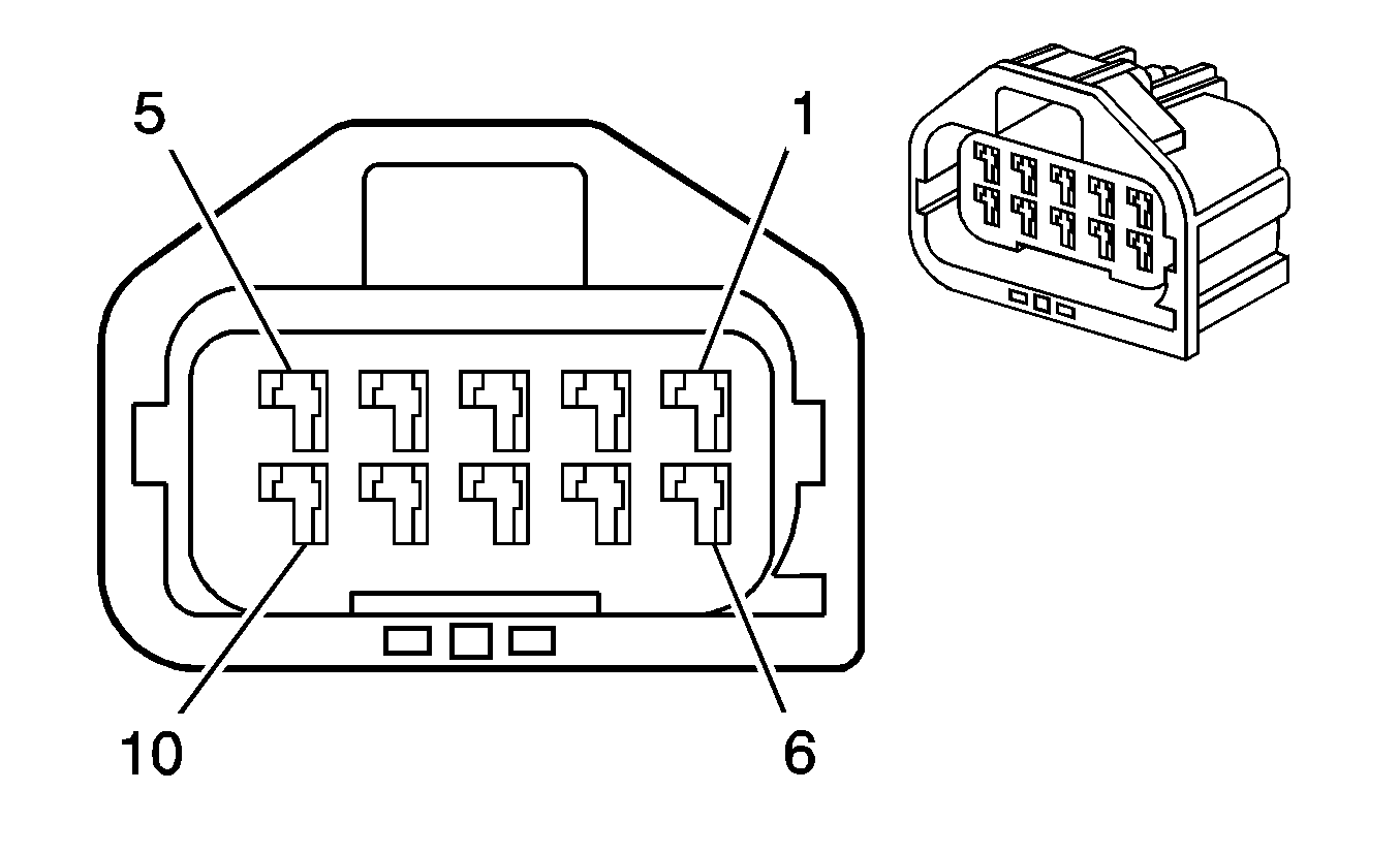
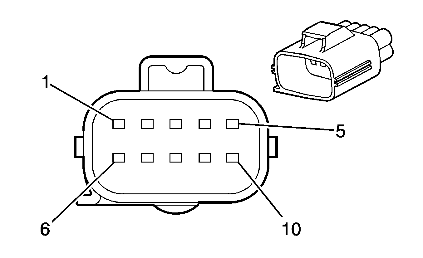
Pin | Wire Color | Circuit No. | Function | Pin | Wire Color | Circuit No. | Function | ||||||||
1 | OG | 5371 | BAS Relay Coil Supply Voltage | 1 | OG | 5371 | BAS Relay Coil Supply Voltage | ||||||||
2 | L-GN/BK | 1338 | Low Reference (JL4/J56) | 2 | L-GN/BK | 1338 | Low Reference (JL4/J56) | ||||||||
3 | GY/BK | 1337 | 5-Volt Reference (JL4/J56) | 3 | GY/BK | 1337 | 5-Volt Reference (JL4/J56) | ||||||||
4 | L-BU | 715 | Lateral Accelerometer Signal (JL4/J56) | 4 | L-BU | 715 | Lateral Accelerometer Signal (JL4/J56) | ||||||||
5 | D-BU | 716 | Yaw Rate Sensor Signal (JL4/J56) | 5 | D-BU | 716 | Yaw Rate Sensor Signal (JL4/J56) | ||||||||
6 | L-GN | 5007 | Backup Lamp Switch Signal (M12/MV1)) | 6 | L-GN | 5007 | Backup Lamp Switch Signal | ||||||||
7 | PU | 5128 | Auxiliary Cooling Fan Relay Control (Export w/V92) | 7 | PU | 5128 | Auxiliary Cooling Fan Relay Control (Export w/V92) | ||||||||
8 | BN | 818 | Vehicle Speed Signal | 8 | BN | 818 | Vehicle Speed Signal | ||||||||
9-10 | -- | -- | Not Used | 9-10 | -- | -- | Not Used | ||||||||
|
| ||||||||||||||
|---|---|---|---|---|---|---|---|---|---|---|---|---|---|---|---|
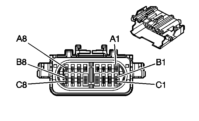
Connector Part Information |
| Connector Part Information |
| ||||||||||||
Pin | Wire Color | Circuit No. | Function | Pin | Wire Color | Circuit No. | Function. | ||||||||
1 | BK/WH | 51 | Ground | 1 | BK/WH | 51 | Ground (LP1/LY7) | ||||||||
BK | 51 | Ground (LS6) | |||||||||||||
2 | BK | 100 | Blunt Cut | 2 | -- | -- | Not Used | ||||||||
|
| ||||||||||||||
|---|---|---|---|---|---|---|---|---|---|---|---|---|---|---|---|
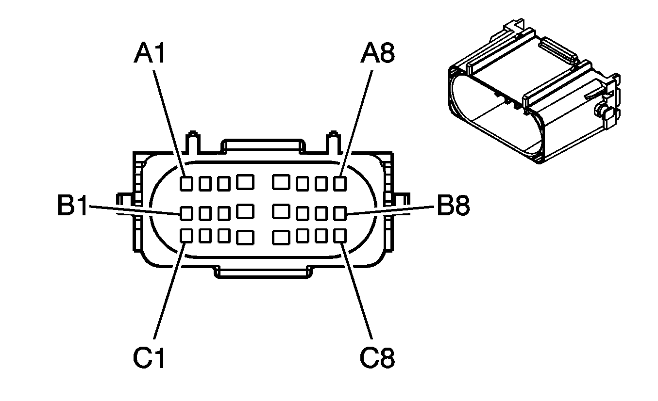
Connector Part Information |
| Connector Part Information |
| ||||||||||||
Pin | Wire Color | Circuit No. | Function | Pin | Wire Color | Circuit No. | Function | ||||||||
A1 | L-GN | 1763 | Steering Wheel Position Signal A (JL4) | A1 | L-GN | 1763 | Steering Wheel Position Signal A (JL4) | ||||||||
A2 | L-BU | 1764 | Steering Wheel Position Signal B (JL4) | A2 | L-BU | 1764 | Steering Wheel Position Signal B (JL4) | ||||||||
A3 | WH | 5359 | 5-Volt Reference | A3 | WH | 5359 | 5-Volt Reference | ||||||||
A4 | BN | 5360 | Low Reference | A4 | BN | 5360 | Low Reference | ||||||||
A5 | YE | 5361 | Brake Pedal Position (BPP) Sensor Signal | A5 | YE | 5361 | Brake Pedal Position (BPP) Sensor Signal | ||||||||
A6 | WH | 2500 | High Speed GMLAN Serial Data Bus + (LY7) | A6 | WH | 2500 | High Speed GMLAN Serial Data Bus + (LY7) | ||||||||
A7 | L-GN | 2501 | High Speed GMLAN Serial Data Bus - (LY7) | A7 | L-GN | 2501 | High Speed GMLAN Serial Data Bus - (LY7) | ||||||||
A8 | PU | 1807 | Class 2 Serial Data | A8 | PU | 1807 | Class 2 Serial Data | ||||||||
B1 | PU | 1272 | Low Reference | B1 | PU | 1272 | Low Reference | ||||||||
B2 | L-BU | 1162 | APP Sensor 2 Signal | B2 | L-BU | 1162 | APP Sensor 2 Signal | ||||||||
B3 | TN | 1274 | 5-Volt Reference | B3 | TN | 1274 | 5-Volt Reference | ||||||||
B4 | BN | 1271 | Low Reference | B4 | BN | 1271 | Low Reference | ||||||||
B5 | D-BU | 1161 | APP Sensor 1 Signal | B5 | D-BU | 1161 | APP Sensor 1 Signal | ||||||||
B6 | WH/BK | 1164 | 5-Volt Reference | B6 | WH/BK | 1164 | 5-Volt Reference | ||||||||
B7 | PK | 839 | Ignition 1 Voltage | B7 | PK | 839 | Ignition 1 Voltage | ||||||||
B8 | BN/WH | 379 | CPP Switch Signal (M35) | B8 | BN/WH | 379 | CPP Switch Signal | ||||||||
C1 | PU | 1807 | Class 2 Serial Data | C1 | PU | 1807 | Class 2 Serial Data | ||||||||
C2 | WH | 121 | Engine Speed Signal | C2 | WH | 121 | Engine Speed Signal | ||||||||
C3 | D-BU | 1537 | ABS Indicator Signal | C3 | D-BU | 1537 | ABS Indicator Signal | ||||||||
C4 | -- | -- | Not Used | C4 | -- | -- | Not Used | ||||||||
C5 | GY | 1884 | Cruise Control Switch Signal (LP1/LY7) | C5 | GY | 1884 | Cruise Control Switch Signal (LP1/LY7) | ||||||||
C6 | YE | 5 | Crank Voltage | C6 | YE | 5 | Crank Voltage | ||||||||
C7 | BN/WH | 419 | MIL Control | C7 | BN/WH | 419 | MIL Control | ||||||||
C8 | PU/WH | 1035 | Starter Relay Coil Supply Voltage (M35) | C8 | PU/WH | 1035 | Starter Relay Coil Supply Voltage | ||||||||
PK | 839 | Ignition 1 Voltage (M82) | |||||||||||||
|
| ||||||||||||||
|---|---|---|---|---|---|---|---|---|---|---|---|---|---|---|---|
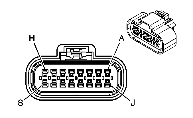
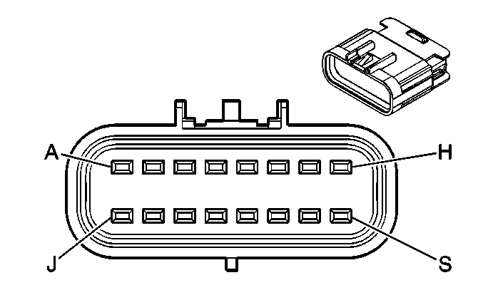
Connector Part Information |
| Connector Part Information |
| ||||||||||||
Pin | Wire Color | Circuit No. | Function | Pin | Wire Color | Circuit No. | Function | ||||||||
A | -- | -- | Not used | A | -- | -- | Not used | ||||||||
B | PU/WH | 1035 | Starter Relay Coil Supply Voltage | B | PU/WH | 1035 | Starter Relay Coil Supply Voltage | ||||||||
C | D-GN/WH | 357 | Oil Temperature Sensor Signal | C | D-GN/WH | 357 | Oil Temperature Sensor Signal | ||||||||
D | WH | 375 | Skip Shift Indicator Control (MN6) | D | WH | 375 | Skip Shift Indicator Control (MN6) | ||||||||
E | -- | -- | Not Used | E | -- | -- | Not Used | ||||||||
F | GY | 397 | Cruise Control On Switch Signal | F | GY | 397 | Cruise Control On Switch Signal | ||||||||
G | D-BU | 84 | Cruise Control Set/Coast Switch Signal | G | D-BU | 84 | Cruise Control Set/Coast Switch Signal | ||||||||
H | GY/BK | 87 | Cruise Control Resume/Accel Switch Signal | H | GY/BK | 87 | Cruise Control Resume/Accel Switch Signal | ||||||||
J | BN/WH | 379 | CPP Switch Signal | J | BN/WH | 379 | CPP Switch Signal | ||||||||
K-L | -- | -- | Not Used | K-L | -- | -- | Not Used | ||||||||
M | BN/WH | 419 | MIL Control | M | BN/WH | 419 | MIL Control | ||||||||
N | -- | -- | Not Used | N | -- | -- | Not Used | ||||||||
P | WH | 121 | Engine Speed Signal | P | WH | 121 | Engine Speed Signal | ||||||||
R | D-BU | 1537 | ABS Indicator Signal | R | D-BU | 1537 | ABS Indicator Signal | ||||||||
S | -- | -- | Not Used | S | -- | -- | Not Used | ||||||||
|
| ||||||||||||||
|---|---|---|---|---|---|---|---|---|---|---|---|---|---|---|---|
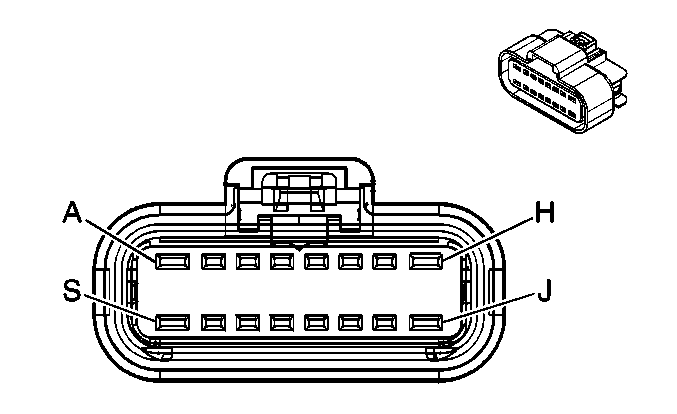
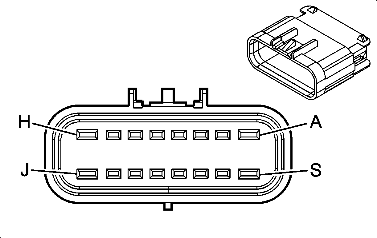
Connector Part Information |
| Connector Part Information |
| ||||||||||||
Pin | Wire Color | Circuit No. | Function | Pin | Wire Color | Circuit No. | Function | ||||||||
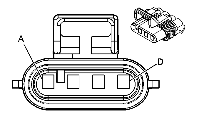
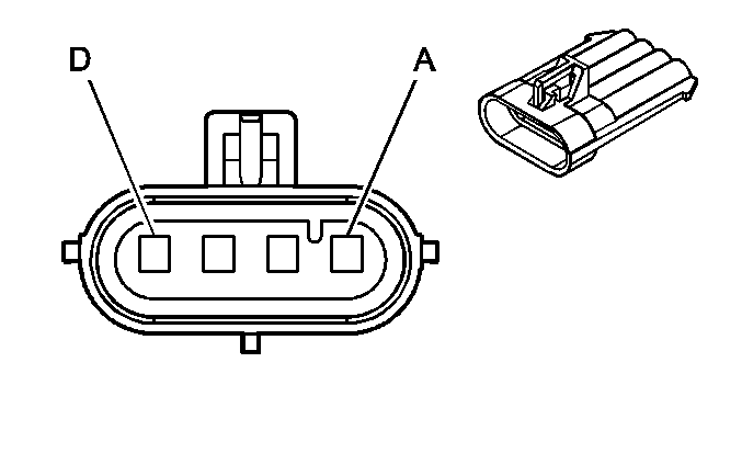
A | YE | 5 | Crank Voltage | A | YE | 5 | Crank Voltage | ||||||||
B-E | -- | -- | Not Used | B-E | -- | -- | Not Used | ||||||||
F | L-GN | 1763 | Steering Wheel Position Signal A | F | L-GN | 1763 | Steering Wheel Position Signal A | ||||||||
G | L-BU | 1764 | Steering Wheel Position Signal B | G | L-BU | 1764 | Steering Wheel Position Signal B | ||||||||
H-J | -- | -- | Not Used | H-J | -- | -- | Not Used | ||||||||
K | WH | 5359 | 5-Volt Reference | K | WH | 5359 | 5-Volt Reference | ||||||||
L | BN | 5360 | Low Reference | L | BN | 5360 | Low Reference | ||||||||
M | YE | 5361 | Brake Pedal Position (BPP) Sensor Signal | M | YE | 5361 | Brake Pedal Position (BPP) Sensor Signal | ||||||||
N | PU | 1807 | Class 2 Serial Data | N | PU | 1807 | Class 2 Serial Data | ||||||||
P | PU | 1807 | Class 2 Serial Data | P | PU | 1807 | Class 2 Serial Data | ||||||||
R-S | -- | -- | Not Used | R-S | -- | -- | Not Used | ||||||||
|
| ||||||||||||||
|---|---|---|---|---|---|---|---|---|---|---|---|---|---|---|---|
Connector Part Information |
| Connector Part Information |
| ||||||||||||
Pin | Wire Color | Circuit No. | Function | Pin | Wire Color | Circuit No. | Function | ||||||||
A | PU | 2234 | Front Fog Lamp Supply Voltage | A | WH | 2234 | Front Fog Lamp Supply Voltage | ||||||||
B | D-BU | 5364 | Left DRL/Turn Supply Voltage (Domestic) | B | WH | 5364 | Left DRL/Turn Supply Voltage (Domestic) | ||||||||
L-BU/WH | 1314 | Left Turn Signal Indicator Lamp Supply Voltage (Export w/T62/T65) | WH | 1314 | Left Turn Signal Indicator Lamp Supply Voltage (Export w/T62/T65) | ||||||||||
C | BK | 250 | Ground | C | WH | 250 | Ground | ||||||||
D | BK | 250 | Ground | D | WH | 250 | Ground | ||||||||

|

| ||||||||||||||
|---|---|---|---|---|---|---|---|---|---|---|---|---|---|---|---|
Connector Part Information |
| Connector Part Information |
| ||||||||||||
Pin | Wire Color | Circuit No. | Function | Pin | Wire Color | Circuit No. | Function | ||||||||
A | PU | 2234 | Front Fog Lamp Supply Voltage | A | WH | 2234 | Front Fog Lamp Supply Voltage | ||||||||
B | D-GN | 5365 | Right DRL/Turn Supply Voltage (Domestic) | B | WH | 5365 | Right DRL/Turn Supply Voltage (Domestic) | ||||||||
D-BU/WH | 1315 | Right Turn Signal Indicator Lamp Supply Voltage (Export w/T62/T65) | WH | 1315 | Right Turn Signal Indicator Lamp Supply Voltage (Export w/T62/T65) | ||||||||||
C | BK | 250 | Ground | C | WH | 250 | Ground | ||||||||
D | BK | 250 | Ground | D | WH | 250 | Ground | ||||||||
|
| ||||||||||||||
|---|---|---|---|---|---|---|---|---|---|---|---|---|---|---|---|
Connector Part Information |
| Connector Part Information |
| ||||||||||||
Pin | Wire Color | Circuit No. | Function | Pin | Wire Color | Circuit No. | Function | ||||||||
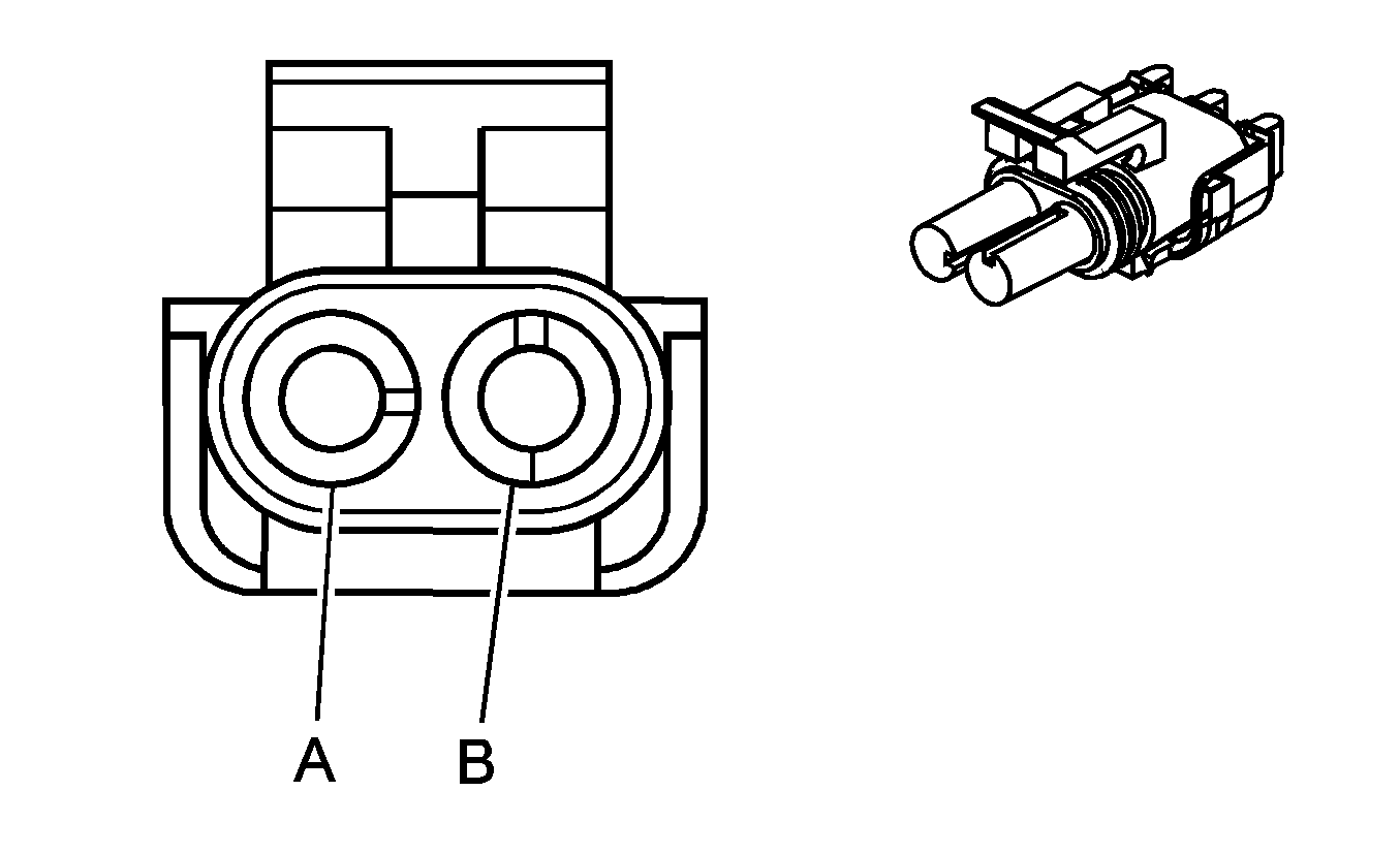
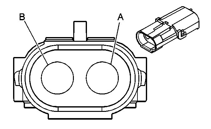
A | L-BU/WH | 1314 | Left Turn Signal Indicator Lamp Supply Voltage | A | L-BU/WH | 1314 | Left Turn Signal Indicator Lamp Supply Voltage | ||||||||
B | BK | 250 | Ground | B | BK | 250 | Ground | ||||||||

|

| ||||||||||||||
|---|---|---|---|---|---|---|---|---|---|---|---|---|---|---|---|
Connector Part Information |
| Connector Part Information |
| ||||||||||||
Pin | Wire Color | Circuit No. | Function | Pin | Wire Color | Circuit No. | Function | ||||||||
A | D-BU/WH | 1315 | Right Turn Signal Indicator Lamp Supply Voltage | A | D-BU/WH | 1315 | Right Turn Signal Indicator Lamp Supply Voltage | ||||||||
B | BK | 250 | Ground | B | BK | 250 | Ground | ||||||||
|
| ||||||||||||||
|---|---|---|---|---|---|---|---|---|---|---|---|---|---|---|---|
Connector Part Information |
| Connector Part Information |
| ||||||||||||
Pin | Wire Color | Circuit No. | Function | Pin | Wire Color | Circuit No. | Function | ||||||||
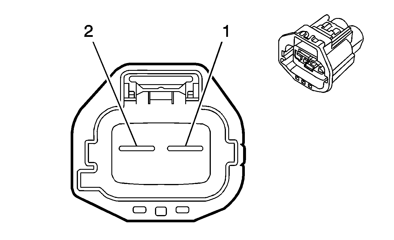
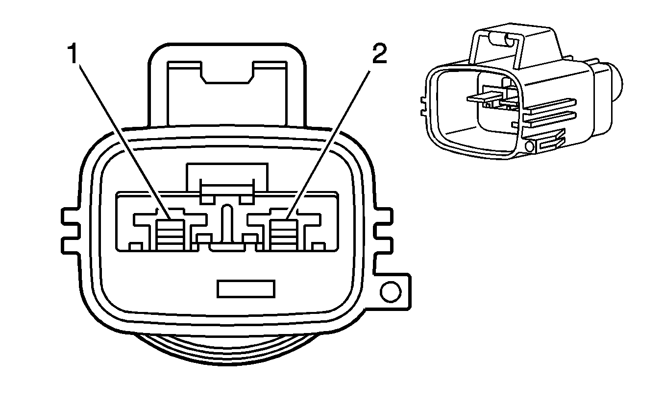
1 | BK | 1150 | Ground | 1 | BK | 1150 | Ground | ||||||||
2 | BK | 1150 | Ground | 2 | BK | 1150 | Ground | ||||||||
|
| ||||||||||||||
|---|---|---|---|---|---|---|---|---|---|---|---|---|---|---|---|
Connector Part Information |
| Connector Part Information |
| ||||||||||||
Pin | Wire Color | Circuit No. | Function | Pin | Wire Color | Circuit No. | Function | ||||||||
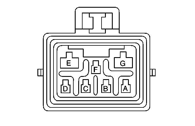
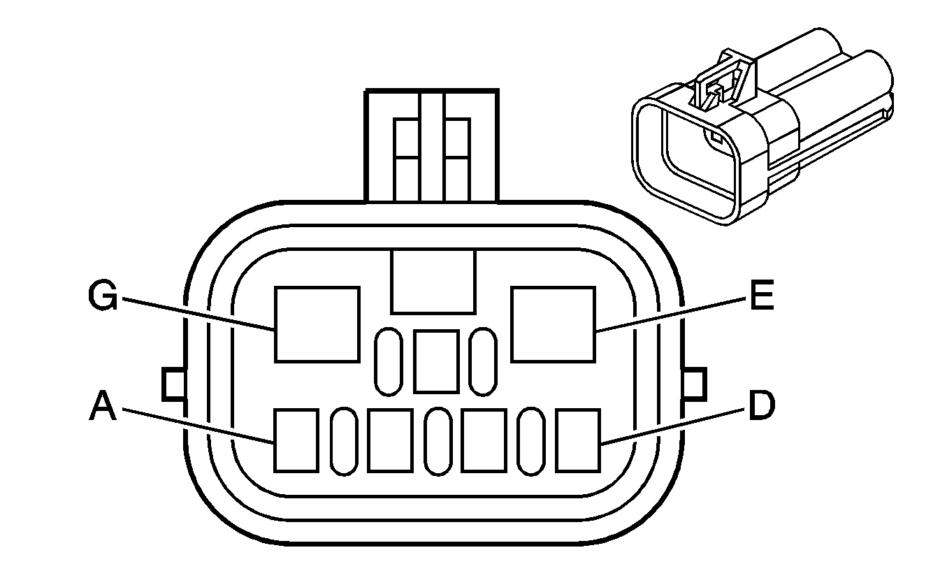
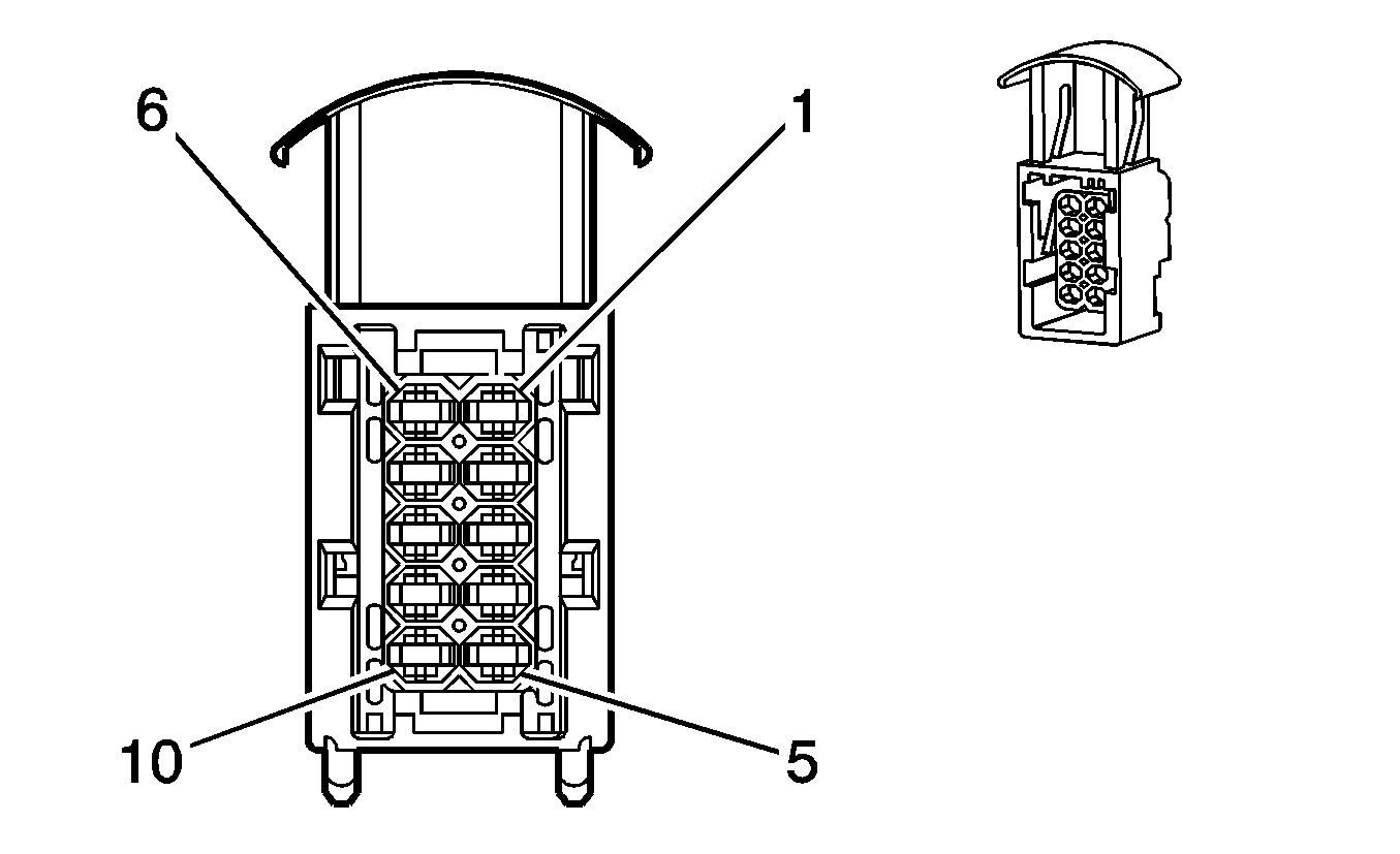
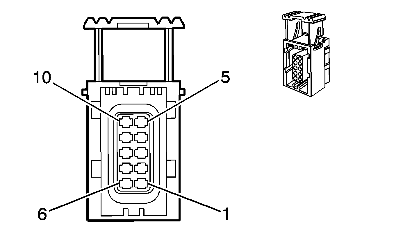
A | PK/BK | 5291 | Ignition 1 Voltage | A | PK/BK | 5291 | Ignition 1 Voltage | ||||||||
B | -- | -- | Not Used | B | -- | -- | Not Used | ||||||||
C | D-GN | 59 | A/C Compressor Clutch Supply Voltage | C | D-GN | 59 | A/C Compressor Clutch Supply Voltage | ||||||||
D | PK/BK | 5292 | Ignition 1 Voltage | D | PK/BK | 5292 | Ignition 1 Voltage | ||||||||
E | PU | 6 | Starter Solenoid Crank Voltage | E | PU | 6 | Starter Solenoid Crank Voltage | ||||||||
F | PK/BK | 5293 | Ignition 1 Voltage | F | PK/BK | 5293 | Ignition 1 Voltage | ||||||||
G | BK/WH | 1451 | Ground (M82) | G | BK/WH | 1451 | Ground (M82) | ||||||||
|
| ||||||||||||||
|---|---|---|---|---|---|---|---|---|---|---|---|---|---|---|---|
Connector Part Information |
| Connector Part Information |
| ||||||||||||
Pin | Wire Color | Circuit No. | Function | Pin | Wire Color | Circuit No. | Function | ||||||||
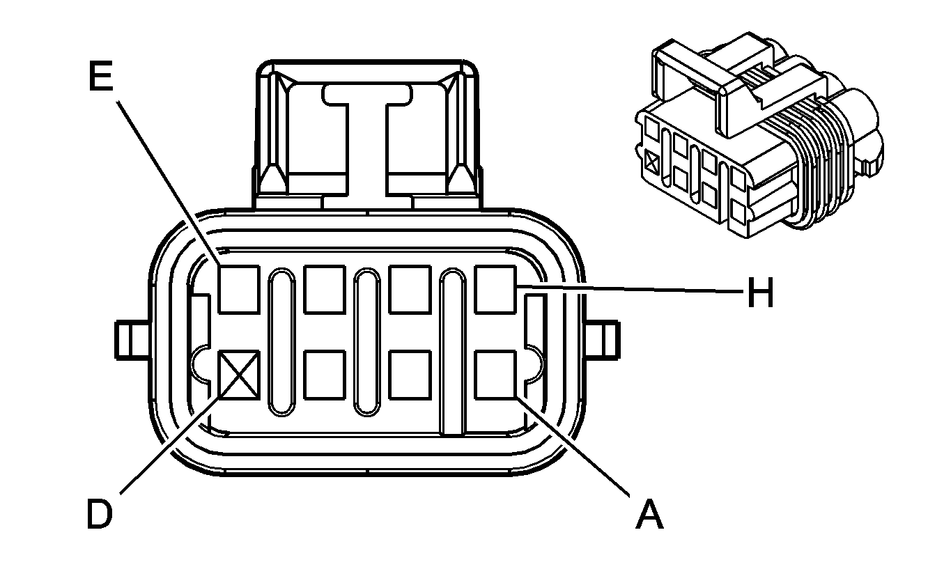
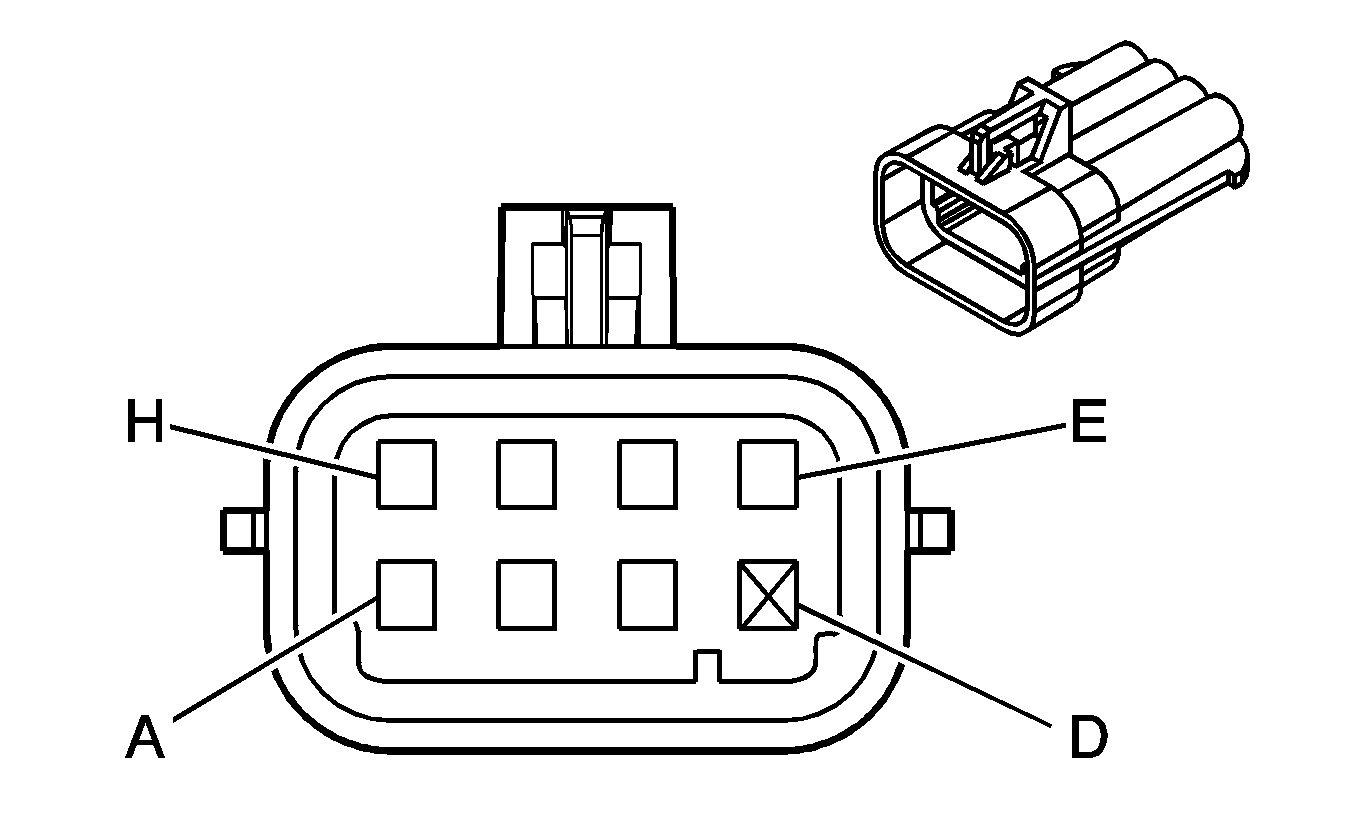
1 | WH | 5291 | Ignition 1 Voltage | 1 | WH | 5291 | Ignition 1 Voltage | ||||||||
2 | WH | 5292 | Ignition 1 Voltage | 2 | WH | 5292 | Ignition 1 Voltage | ||||||||
3 | TN | 1744 | Fuel Injector 1 Control | 3 | TN | 1744 | Fuel Injector 1 Control | ||||||||
4 | PK/BK | 1746 | Fuel Injector 3 Control | 4 | PK/BK | 1746 | Fuel Injector 3 Control | ||||||||
5 | TN/WH | 845 | Fuel Injector 5 Control | 5 | TN/WH | 845 | Fuel Injector 5 Control | ||||||||
6 | L-GN/BK | 1745 | Fuel Injector 2 Control | 6 | L-GN/BK | 1745 | Fuel Injector 2 Control | ||||||||
7 | D-BU/BK | 844 | Fuel Injector 4 Control | 7 | L-BU/BK | 844 | Fuel Injector 4 Control | ||||||||
8 | YE/BK | 846 | Fuel Injector 6 Control | 8 | YE/BK | 846 | Fuel Injector 6 Control | ||||||||
9-10 | -- | -- | Not Used | 9-10 | -- | -- | Not Used | ||||||||
|
| ||||||||||||||
|---|---|---|---|---|---|---|---|---|---|---|---|---|---|---|---|
Connector Part Information |
| Connector Part Information |
| ||||||||||||
Pin | Wire Color | Circuit No. | Function | Pin | Wire Color | Circuit No. | Function | ||||||||
A | BK/WH | 1451 | Ground | A | BK | 1451 | Ground | ||||||||
B | OG | 2127 | IC 7 Control | B | RD | 2127 | IC 7 Control | ||||||||
C | D-GN | 2125 | IC 5 Control | C | D-GN | 2125 | IC 5 Control | ||||||||
D | -- | -- | Unavailable | D | -- | -- | Unavailable | ||||||||
E | BN | 2129 | Low Reference | E | BN | 2129 | Low Reference | ||||||||
F | L-BU | 2123 | IC 3 Control | F | L-BU | 2123 | IC 3 Control | ||||||||
G | PU | 2121 | IC 1 Control | G | PU | 2121 | IC 1 Control | ||||||||
H | PK/BK | 5291 | Ignition 1 Voltage | H | PK | 5291 | Ignition 1 Voltage | ||||||||

|

| ||||||||||||||
|---|---|---|---|---|---|---|---|---|---|---|---|---|---|---|---|
Connector Part Information |
| Connector Part Information |
| ||||||||||||
Pin | Wire Color | Circuit No. | Function | Pin | Wire Color | Circuit No. | Function | ||||||||
A | BK/WH | 1551 | Ground | A | BK | 1551 | Ground | ||||||||
B | RD/WH | 2122 | IC 2 Control | B | RD | 2122 | IC 2 Control | ||||||||
C | D-GN/WH | 2124 | IC 4 Control | C | D-GN | 2124 | IC 4 Control | ||||||||
D | -- | -- | Unavailable | D | -- | -- | Unavailable | ||||||||
E | BN/WH | 2130 | Low Reference | E | BN | 2130 | Low Reference | ||||||||
F | L-BU/WH | 2126 | IC 6 Control | F | L-BU | 2126 | IC 6 Control | ||||||||
G | PU/WH | 2128 | IC 8 Control | G | PU | 2128 | IC 8 Control | ||||||||
H | PK/BK | 5292 | Ignition 1 Voltage | H | PK | 5292 | Ignition 1 Voltage | ||||||||
|
| ||||||||||||||
|---|---|---|---|---|---|---|---|---|---|---|---|---|---|---|---|
Connector Part Information |
| Connector Part Information |
| ||||||||||||
Pin | Wire Color | Circuit No. | Function | Pin | Wire Color | Circuit No. | Function | ||||||||
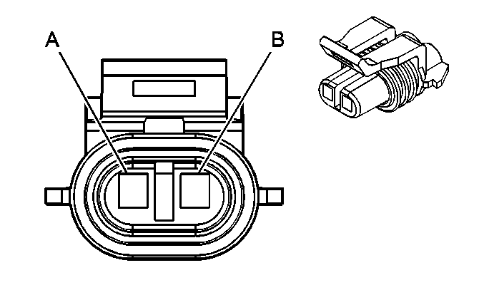
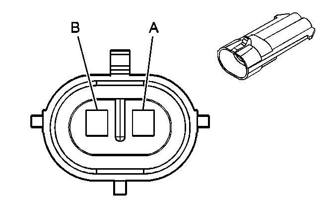
A | D-BU | 496 | Knock Sensor 1 Signal | A | D-BU | 496 | Knock Sensor 1 Signal | ||||||||
B | L-BU | 1876 | Knock Sensor 2 Signal | B | L-BU | 1876 | Knock Sensor 2 Signal | ||||||||
|
| ||||||||||||||
|---|---|---|---|---|---|---|---|---|---|---|---|---|---|---|---|
Connector Part Information |
| Connector Part Information |
| ||||||||||||
Pin | Wire Color | Circuit No. | Function | Pin | Wire Color | Circuit No. | Function | ||||||||
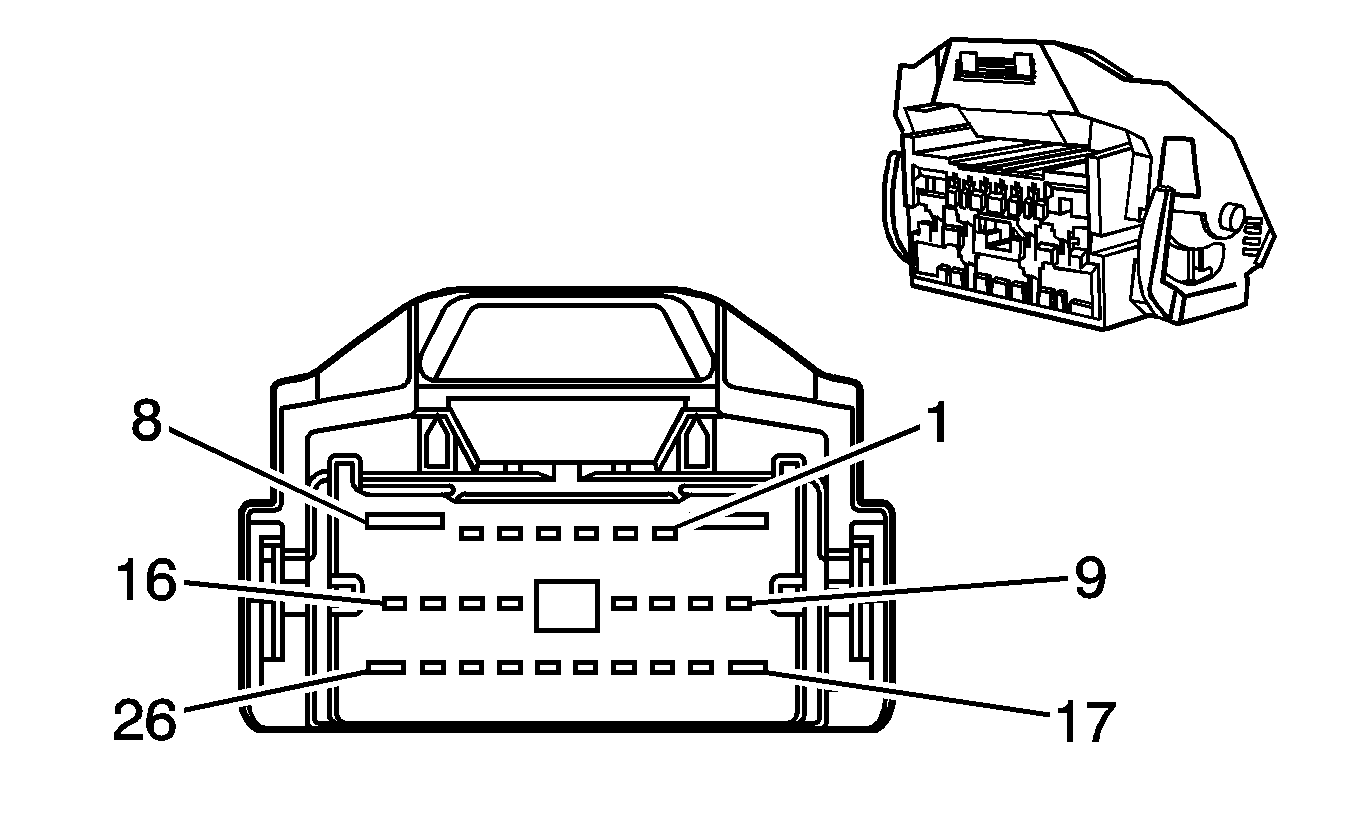
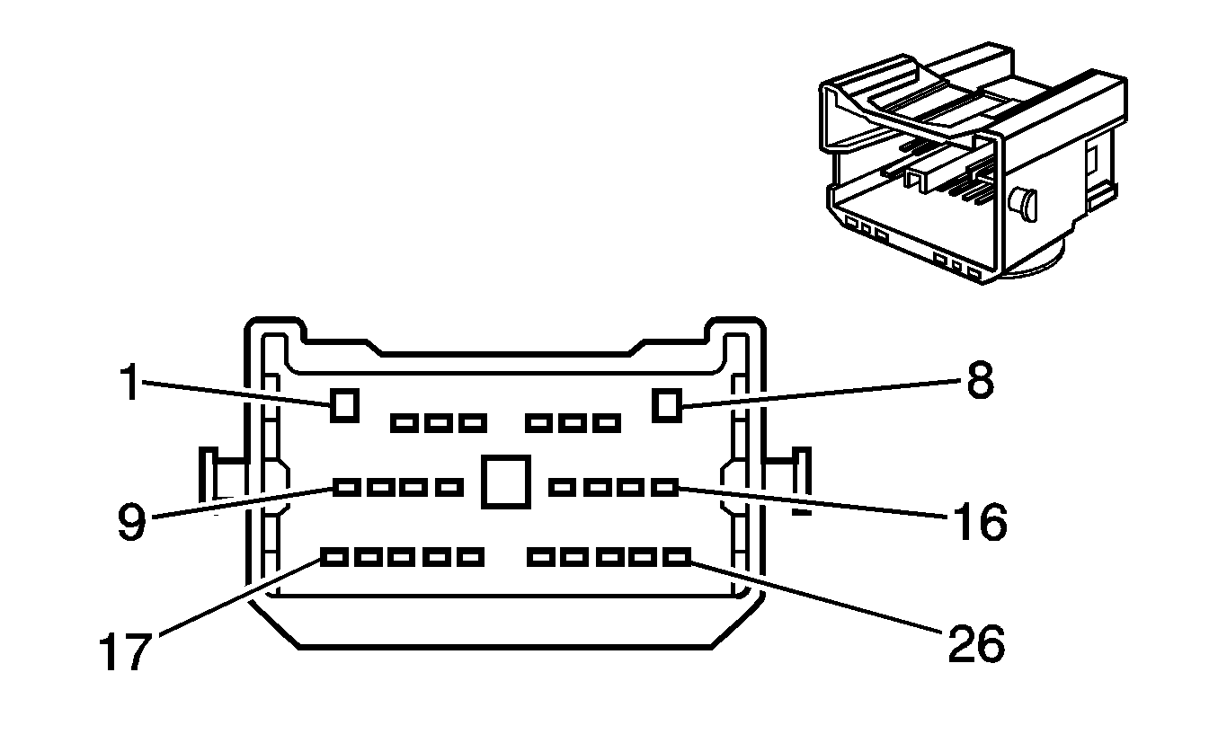
1 | BK | 350 | Ground | 1 | BK | 350 | Ground | ||||||||
2 | PU | 1807 | Class 2 Serial Data | 2 | PU | 1807 | Class 2 Serial Data | ||||||||
3 | BK/WH | 351 | Ground | 3 | BK/WH | 351 | Ground | ||||||||
4 | -- | -- | Not Used | 4 | -- | -- | Not Used | ||||||||
5 | PK/BK | 1597 | Courtesy Lamps Switch On Signal | 5 | PK/BK | 1597 | Courtesy Lamps Switch On Signal | ||||||||
6 | YE | 1834 | Forward Discriminating Sensor Signal | 6 | YE | 1834 | Forward Discriminating Sensor Signal | ||||||||
7 | TN/OG | 5045 | Discriminating Sensor - Low Reference | 7 | TN/OG | 5045 | Discriminating Sensor - Low Reference | ||||||||
8 | D-BU/WH | 1315 | Right Turn Signal Indicator Lamp Supply Voltage | 8 | D-BU/WH | 1315 | Right Turn Signal Indicator Lamp Supply Voltage | ||||||||
D-BU/WH | 1315 | Right Turn Signal Indicator Lamp Supply Voltage | |||||||||||||
9 | D-BU/WH | 149 | Courtesy Lamp Supply Voltage | 9 | D-BU/WH | 149 | Courtesy Lamp Supply Voltage | ||||||||
D-BU/WH | 149 | Courtesy Lamp Supply Voltage | |||||||||||||
10 | GY | 157 | Courtesy Lamp Control | 10 | GY | 157 | Courtesy Lamp Control | ||||||||
GY | 157 | Courtesy Lamp Control | |||||||||||||
11 | YE | 32 | Instrument Panel Lamp Fuse Supply Voltage 1 (w/o T79) | 11 | YE | 32 | Instrument Panel Lamp Fuse Supply Voltage 1 (w/o T79) | ||||||||
12 | PU | 709 | Left Park Lamp Supply Voltage (w/o T79) | 12 | PU | 709 | Left Park Lamp Supply Voltage (w/o T79) | ||||||||
13 | D-GN | 44 | Instrument Panel Lamps Dimmer Switch Signal | 13 | D-GN | 44 | Instrument Panel Lamps Dimmer Switch Signal | ||||||||
14 | YE | 5005 | Instrument Panel Lamps Dimmer Switch Low Reference | 14 | YE | 5005 | Instrument Panel Lamps Dimmer Switch Low Reference | ||||||||
15 | OG | 300 | Ignition 3 Voltage | 15 | OG | 300 | Ignition 3 Voltage | ||||||||
16 | PK | 3 | Ignition 1 Voltage | 16 | PK | 3 | Ignition 1 Voltage | ||||||||
17 | L-BU/WH | 1314 | Left Turn Signal Indicator Lamp Supply Voltage | 17 | L-BU/WH | 1314 | Left Turn Signal Indicator Lamp Supply Voltage | ||||||||
18 | L-BU/BK | 1688 | 5-Volt Reference | 18 | L-BU/BK | 1688 | 5-Volt Reference | ||||||||
19 | PU/WH | 5025 | Ignition Lock Cylinder Control Actuator Supply Voltage | 19 | PU/WH | 5025 | Ignition Lock Cylinder Control Actuator Supply Voltage | ||||||||
20-21 | -- | -- | Not Used | 20-21 | -- | -- | Not Used | ||||||||
22 | BN | 41 | Ignition 3 Voltage | 22 | BN | 41 | Ignition 3 Voltage | ||||||||
23 | -- | -- | Not Used | 23 | -- | -- | Not Used | ||||||||
24 | BN | 141 | Ignition 3 Voltage | 24 | BN | 141 | Ignition 3 Voltage | ||||||||
25 | PK/BK | 5292 | Ignition 1 Voltage | 25 | PK/BK | 5292 | Ignition 1 Voltage | ||||||||
26 | -- | -- | Not Used | 26 | -- | -- | Not Used | ||||||||

|

| ||||||||||||||
|---|---|---|---|---|---|---|---|---|---|---|---|---|---|---|---|
Connector Part Information |
| Connector Part Information |
| ||||||||||||
Pin | Wire Color | Circuit No. | Function | Pin | Wire Color | Circuit No. | Function | ||||||||
1 | BK | 450 | Ground | 1 | BK | 450 | Ground | ||||||||
2 | -- | -- | Not Used | 2 | -- | -- | Not Used | ||||||||
3 | GY/BK | 1337 | 5-Volt Reference (JL4/J56) | 3 | GY/BK | 1337 | 5-Volt Reference (JL4/J56) | ||||||||
GY/BK | 1337 | 5-Volt Reference (JL4/J56) | |||||||||||||
4 | L-GN/BK | 1338 | Low Reference (JL4/J56) | 4 | L-GN/BK | 1338 | Low Reference (JL4/J56) | ||||||||
L-GN/BK | 1338 | Low Reference (JL4/J56) | |||||||||||||
5 | PU | 1807 | Class 2 Serial Data | 5 | PU | 1807 | Class 2 Serial Data | ||||||||
6 | RD/WH | 540 | Battery Positive Voltage | 6 | RD/WH | 540 | Battery Positive Voltage | ||||||||
7 | BN | 818 | Vehicle Speed Signal | 7 | BN | 818 | Vehicle Speed Signal | ||||||||
BN | 818 | Vehicle Speed Signal | |||||||||||||
8 | YE | 5358 | Auxiliary Cooling Fan Motor Supply Voltage (V92) | 8 | YE | 5358 | Auxiliary Cooling Fan Motor Supply Voltage (V92) | ||||||||
9 | -- | -- | Not Used | 9 | -- | -- | Not Used | ||||||||
10 | YE | 1491 | Backlight Lamps Control | 10 | YE | 1491 | Backlight Lamps Control | ||||||||
11 | BN/WH | 309 | Right Park Lamp Supply Voltage (w/o T79) | 11 | BN/WH | 309 | Right Park Lamp Supply Voltage (w/o T79) | ||||||||
12-13 | -- | -- | Not Used | 12-13 | -- | -- | Not Used | ||||||||
14 | BK/WH | 451 | Ground | 14 | BK/WH | 451 | Ground | ||||||||
15-16 | -- | -- | Not Used | 15-16 | -- | -- | Not Used | ||||||||
17 | D-BU/WH | 149 | Courtesy Lamp Supply Voltage | 17 | D-BU/WH | 149 | Courtesy Lamp Supply Voltage | ||||||||
D-BU/WH | 149 | Courtesy Lamp Supply Voltage | |||||||||||||
18 | GY | 157 | Courtesy Lamp Control | 18 | GY | 157 | Courtesy Lamp Control | ||||||||
GY | 157 | Courtesy Lamp Control | |||||||||||||
19-22 | -- | -- | Not Used | 19-22 | -- | -- | Not Used | ||||||||
23 | BN/WH | 1571 | Traction Control Switch Signal | 23 | BN/WH | 1571 | Traction Control Switch Signal | ||||||||
24-25 | -- | -- | Not Used | 24-25 | -- | -- | Not Used | ||||||||
26 | TN | 5026 | Ignition Lock Cylinder Control Switch Signal (M82) | 26 | TN | 5026 | Ignition Lock Cylinder Control Switch Signal (M82) | ||||||||
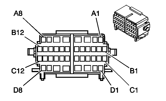
|
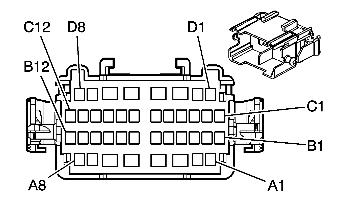
| ||||||||||||||
|---|---|---|---|---|---|---|---|---|---|---|---|---|---|---|---|
Connector Part Information |
| Connector Part Information |
| ||||||||||||
Pin | Wire Color | Circuit No. | Function | Pin | Wire Color | Circuit No. | Function | ||||||||
A1 | BN | 1356 | Flash To Pass Switch Signal | A1 | BN | 1356 | Flash To Pass Switch Signal | ||||||||
A2 | BK | 351 | Ground | A2 | BK | 351 | Ground | ||||||||
A3 | TN/WH | 1969 | Headlamp High Beam Relay Control | A3 | BK/WH | 1969 | Headlamp High Beam Relay Control | ||||||||
TN/WH | 1969 | Headlamp High Beam Relay Control | |||||||||||||
A4 | PK/WH | 1970 | Headlamp Low Beam Relay Control | A4 | L-BU | 1970 | Headlamp Low Beam Relay Control | ||||||||
PK/WH | 1970 | Headlamp Low Beam Relay Control | |||||||||||||
A5 | TN | 28 | Horn Relay Control | A5 | L-GN | 28 | Horn Relay Control | ||||||||
TN | 28 | Horn Relay Control | |||||||||||||
A6 | BK/WH | 351 | Ground | A6 | BK/WH | 351 | Ground | ||||||||
A7 | PU | 1807 | Class 2 Serial Data | A7 | PU | 1807 | Class 2 Serial Data | ||||||||
A8 | PK | 1545 | Information Down Switch Signal (LP1/LY7) | A8 | PK | 1545 | Information Down Switch Signal (LP1/LY7) | ||||||||
GY | 397 | Cruise Control On Switch Signal (LS6) | 397 | Cruise Control On Switch Signal (LS6) | |||||||||||
B1 | L-BU | 187 | Rear Fog Lamp Switch Signal (w/T79) | B1 | L-BU | 187 | Rear Fog Lamp Switch Signal | ||||||||
B2 | OG | 192 | Front Fog Lamp Switch Signal | B2 | OG | 192 | Front Fog Lamp Switch Signal | ||||||||
B3 | WH | 103 | Headlamp Switch Headlamps On Signal | B3 | WH | 103 | Headlamp Switch Headlamps On Signal | ||||||||
B4 | BN/WH | 301 | Park Lamp Switch On Signal | B4 | BN/WH | 301 | Park Lamp Switch On Signal | ||||||||
B5 | PU | 1783 | Twilight Sentinel Delay Signal | B5 | PU | 1783 | Twilight Sentinel Delay Signal | ||||||||
B6 | -- | -- | Not Used | B6 | -- | -- | Not Used | ||||||||
B7 | D-GN | 80 | Key In Ignition Switch Signal | B7 | L-GN | 80 | Key In Ignition Switch Signal | ||||||||
B8 | D-BU | 477 | Windshield Wiper Switch Signal 1 | B8 | D-BU | 477 | Windshield Wiper Switch Signal 1 | ||||||||
B9 | PU | 92 | Windshield Wiper Motor High Speed | B9 | PU | 92 | Windshield Wiper Motor High Speed | ||||||||
B10 | WH | 1538 | Windshield Wiper Switch On Signal | B10 | WH | 1538 | Windshield Wiper Switch On Signal | ||||||||
B11 | YE | 43 | Accessory Voltage | B11 | YE | 43 | Accessory Voltage | ||||||||
B12 | GY | 478 | Windshield Wiper Switch Signal 2 | B12 | GY | 478 | Windshield Wiper Switch Signal 2 | ||||||||
C1 | PU | 1375 | Remote Radio Control Supply Voltage (LP1/LY7) | C1 | PU | 1375 | Remote Radio Control Supply Voltage (LP1/LY7) | ||||||||
D-BU | 84 | Cruise Control Set/Coast Switch Signal (LS6) | 84 | Cruise Control Set/Coast Switch Signal (LS6) | |||||||||||
C2 | RD/WH | 1440 | Battery Positive Voltage | C2 | OG | 1440 | Battery Positive Voltage | ||||||||
C3 | YE | 343 | Accessory Voltage | C3 | YE | 343 | Accessory Voltage | ||||||||
C4 | YE | 1491 | Backlight Lamps Control | C4 | YE | 1491 | Backlight Lamps Control | ||||||||
C5 | BK | 350 | Ground | C5 | BK | 350 | Ground | ||||||||
C6 | PU/WH | 5025 | Ignition Lock Cylinder Control Actuator Supply Voltage (M82) | C6 | PU/WH | 5025 | Ignition Lock Cylinder Control Actuator Supply Voltage (M82) | ||||||||
C7 | L-BU/WH | 1414 | Left Turn Signal Switch Signal (w/o T62/T65) | C7 | L-BU/WH | 1414 | Left Turn Signal Switch Signal (w/o T62/T65) | ||||||||
C8 | D-BU/WH | 1415 | Right Turn Signal Switch Signal (w/o T62/T65) | C8 | D-BU/WH | 1415 | Right Turn Signal Switch Signal (w/o T62/T65) | ||||||||
C9 | PK | 3 | Ignition 1 Voltage | C9 | PK | 3 | Ignition 1 Voltage | ||||||||
C10 | YE | 5 | Crank Voltage | C10 | YE | 5 | Crank Voltage | ||||||||
C11 | OG | 300 | Ignition 3 Voltage | C11 | OG | 300 | Ignition 3 Voltage | ||||||||
C12 | D-BU | 1796 | Steering Wheel Controls Signal (LP1/LY7) | C12 | D-BU | 1796 | Steering Wheel Controls Signal (LP1/LY7) | ||||||||
901 | Steering Wheel Controls Signal (LS6) | 5201 | Steering Wheel Controls Signal (LS6) | ||||||||||||
D1 | OG | 1544 | Information Up Switch Signal (LP1/LY7) | D1 | OG | 1544 | Information Up Switch Signal (LP1/LY7) | ||||||||
GY/BK | 87 | Cruise Control Resume/Accel Switch Signal (LS6) | 87 | Cruise Control Resume/Accel Switch Signal (LS6) | |||||||||||
D2 | GY | 1884 | Cruise Control Switch Signal (LP1/LY7) | D2 | GY | 1884 | Cruise Control Switch Signal (LP1/LY7) | ||||||||
GY/BK | 1884 | Cruise Control Switch Signal (LS6) | |||||||||||||
D3 | RD/WH | 540 | Battery Positive Voltage | D3 | RD/WH | 540 | Battery Positive Voltage | ||||||||
D4 | RD/WH | 1940 | Battery Positive Voltage | D4 | RD/WH | 1940 | Battery Positive Voltage | ||||||||
D5 | PK | 339 | Ignition 1 Voltage | D5 | PK | 339 | Ignition 1 Voltage | ||||||||
D6 | BN | 4 | Accessory Voltage | D6 | BN | 4 | Accessory Voltage | ||||||||
BN | 4 | Accessory Voltage | |||||||||||||
D7 | YE/BK | 1418 | Left Rear Turn Signal Switch Signal (T79) | D7 | YE/BK | 1418 | Left Rear Turn Signal Switch Signal | ||||||||
D8 | D-GN/WH | 1419 | Right Rear Turn Signal Switch Signal (T79) | D8 | L-GN | 1419 | Right Rear Turn Signal Switch Signal | ||||||||
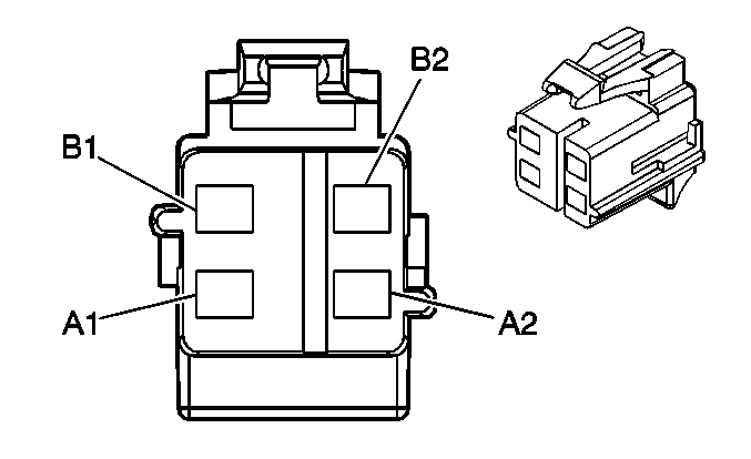
|
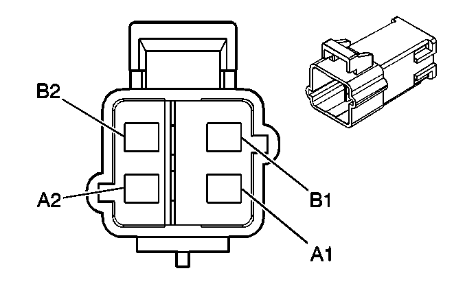
| ||||||||||||||
|---|---|---|---|---|---|---|---|---|---|---|---|---|---|---|---|
Connector Part Information |
| Connector Part Information |
| ||||||||||||
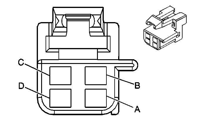
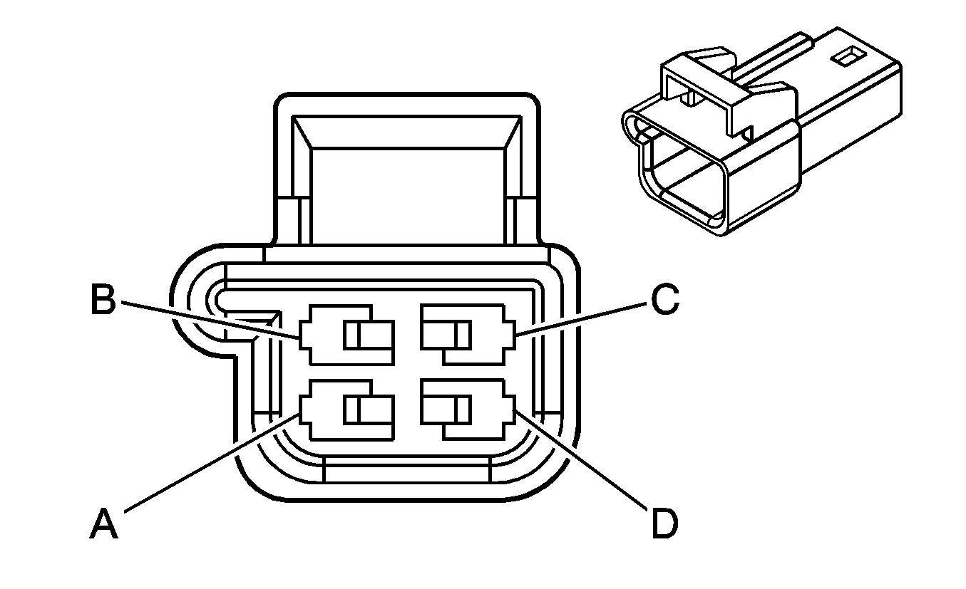
Pin | Wire Color | Circuit No. | Function | Pin | Wire Color | Circuit No. | Function | ||||||||
A1 | TN | 3021 | Steering Wheel Module - Stage 1 - High Control | A1 | TN | 3021 | Steering Wheel Module - Stage 1 - High Control | ||||||||
A2 | BN | 3020 | Steering Wheel Module - Stage 1 - Low Control | A2 | BN | 3020 | Steering Wheel Module - Stage 1 - Low Control | ||||||||
B1 | WH | 3023 | Steering Wheel Module - Stage 2 - High Control | B1 | WH | 3023 | Steering Wheel Module - Stage 2 - High Control | ||||||||
B2 | PK | 3022 | Steering Wheel Module - Stage 2 - Low Control | B2 | PK | 3022 | Steering Wheel Module - Stage 2 - Low Control | ||||||||
|
| ||||||||||||||
|---|---|---|---|---|---|---|---|---|---|---|---|---|---|---|---|
Connector Part Information |
| Connector Part Information |
| ||||||||||||
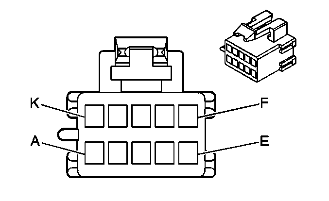
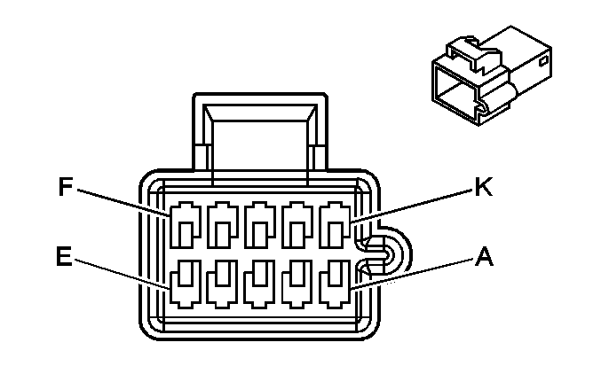
Pin | Wire Color | Circuit No. | Function | Pin | Wire Color | Circuit No. | Function | ||||||||
A | L-BU/BK | 590 | Left Sunload Sensor Signal | A | L-BU/BK | 590 | Left Sunload Sensor Signal | ||||||||
B | GY | 1548 | Right Sunload Sensor Signal | B | GY | 1548 | Right Sunload Sensor Signal | ||||||||
C | YE | 61 | Low Reference | C | YE | 61 | Low Reference | ||||||||
D | WH | 278 | Ambient Light Sensor Signal | D | WH | 278 | Ambient Light Sensor Signal | ||||||||
|
| ||||||||||||||
|---|---|---|---|---|---|---|---|---|---|---|---|---|---|---|---|
Connector Part Information |
| Connector Part Information |
| ||||||||||||
Pin | Wire Color | Circuit No. | Function | Pin | Wire Color | Circuit No. | Function | ||||||||
A | OG | 1544 | Information Up Switch Signal | A | OG | 1544 | Information Up Switch Signal | ||||||||
87 | Cruise Control Resume/Accel Switch Signal (LS6) | GY/WH | 87 | Cruise Control Resume/Accel Switch Signal (LS6) | |||||||||||
B | PK | 339 | Ignition 1 Voltage | B | PK | 339 | Ignition 1 Voltage (LS6) | ||||||||
C | PK | 1545 | Information Down Switch Signal | C | PK | 1545 | Information Down Switch Signal | ||||||||
397 | Cruise Control On Switch Signal (LS6) | GY | 397 | Cruise Control On Switch Signal (LS6) | |||||||||||
D | BK | 351 | Ground (LS6) | D | BK | 351 | Ground (LS6) | ||||||||
E | PU | 1375 | Remote Radio Control Supply Voltage (LP1/LY7) | E | PU | 1375 | Remote Radio Control Supply Voltage (LP1/LY7) | ||||||||
84 | Cruise Control Set/Coast Switch Signal (LS6) | D-BU | 84 | Cruise Control Set/Coast Switch Signal (LS6) | |||||||||||
F | YE | 1491 | Backlight Lamps Control | F | YE | 1491 | Backlight Lamps Control | ||||||||
YE | 1491 | Backlight Lamps Control | |||||||||||||
G | D-BU | 1796 | Steering Wheel Controls Signal (LP1/LY7) | G | D-BU | 1796 | Steering Wheel Controls Signal (LP1/LY7) | ||||||||
1796 | Steering Wheel Controls Signal (LP1/LY7) | ||||||||||||||
5201 | Steering Wheel Controls Signal (LS6) | 5201 | Steering Wheel Controls Signal (LS6) | ||||||||||||
H | BK | 350 | Ground | H | BK | 350 | Ground | ||||||||
BK | 350 | Ground | |||||||||||||
J | L-GN | 28 | Horn Relay Control | J | TN | 28 | Horn Relay Control | ||||||||
K | -- | -- | Not Used | K | -- | -- | Not Used | ||||||||
|
| ||||||||||||||
|---|---|---|---|---|---|---|---|---|---|---|---|---|---|---|---|
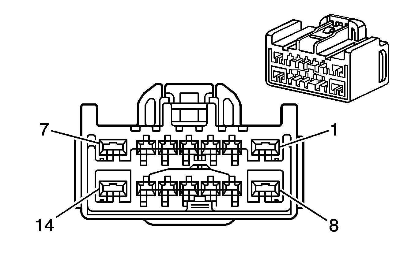
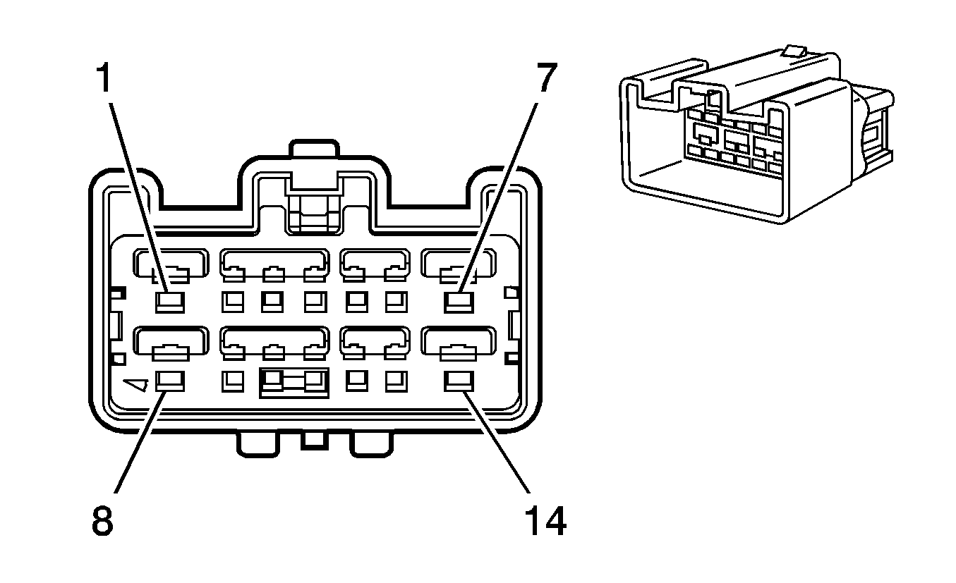
Connector Part Information |
| Connector Part Information |
| ||||||||||||
Pin | Wire Color | Circuit No. | Function | Pin | Wire Color | Circuit No. | Function | ||||||||
1 | RD/WH | 3740 | Battery Positive Voltage | 1 | OG | 3740 | Battery Positive Voltage | ||||||||
2 | RD/WH | 2440 | Battery Positive Voltage (KA1) | 2 | OG | 2440 | Battery Positive Voltage (KA1) | ||||||||
3 | PK | 1501 | Driver Heated Seat High/Low Signal (KA1) | 3 | PK | 1501 | Driver Heated Seat High/Low Signal (KA1) | ||||||||
4 | L-BU/WH | 181 | Heated Seat Control Module Status Signal (KA1) | 4 | L-BU/WH | 181 | Heated Seat Control Module Status Signal (KA1) | ||||||||
5-7 | -- | -- | Not Used | 5-7 | -- | -- | Not Used | ||||||||
8 | RD/WH | 2840 | Battery Positive Voltage (A45) | 8 | OG | 2840 | Battery Positive Voltage (A45) | ||||||||
9 | BN | 41 | Ignition 3 Voltage (KA1) | 9 | BN | 41 | Ignition 3 Voltage (KA1) | ||||||||
10 | -- | -- | Not Used | 10 | -- | -- | Not Used | ||||||||
11 | PU | 1807 | Class 2 Serial Data (A45) | 11 | PU | 1807 | Class 2 Serial Data (A45) | ||||||||
12 | PK | 5017 | Seat Belt Switch - Driver - Low Reference | 12 | BK | 5017 | Seat Belt Switch - Driver - Low Reference | ||||||||
13 | TN/WH | 238 | Seat Belt Switch - Driver - Signal | 13 | BK/WH | 238 | Seat Belt Switch - Driver - Signal | ||||||||
14 | BK | 550 | Ground (AH8/KA1) | 14 | BK | 550 | Ground (AH8/KA1) | ||||||||
|
| ||||||||||||||||||
|---|---|---|---|---|---|---|---|---|---|---|---|---|---|---|---|---|---|---|---|
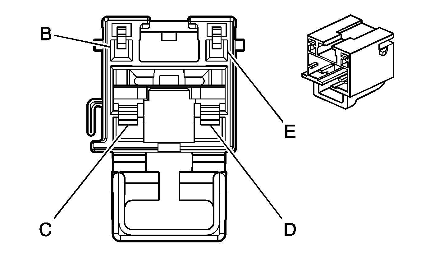
| |||||||||||||||||||
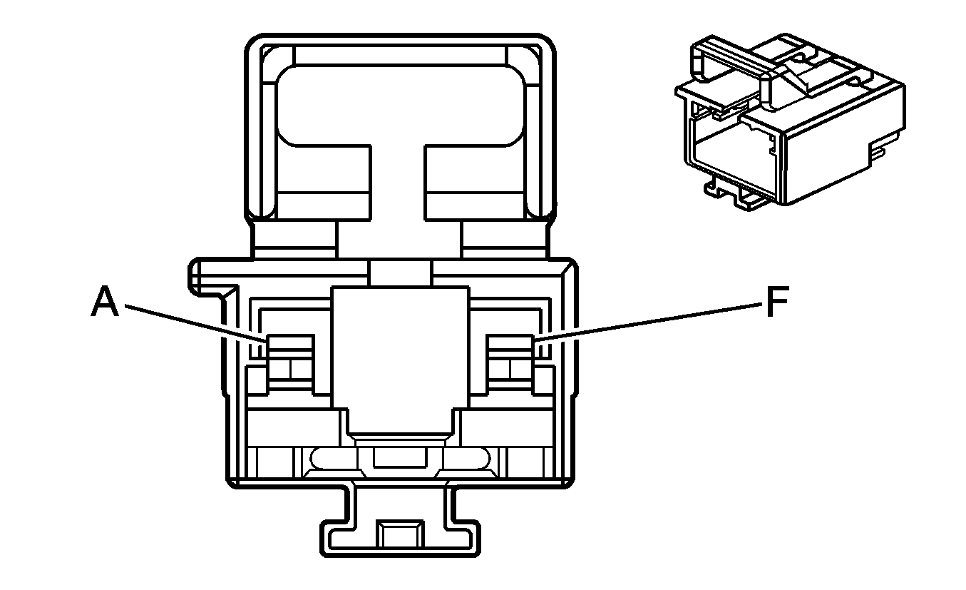
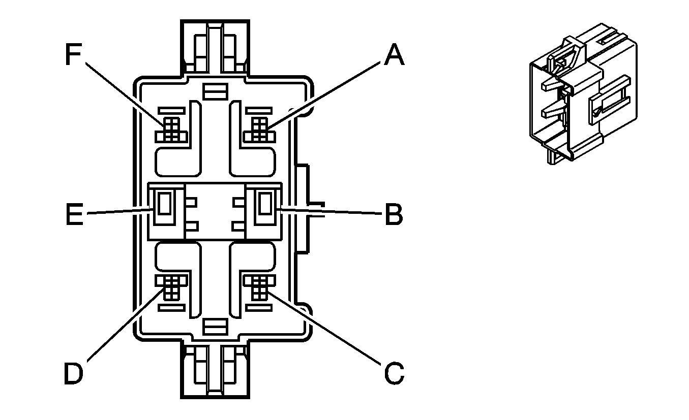
Connector Part Information |
| Connector Part Information |
| ||||||||||||||||
Pin | Wire Color | Circuit No. | Function | Pin | Wire Color | Circuit No. | Function | ||||||||||||
A | BK | 2118 | Seat Belt Pretensioner - Driver - High Control | A | TN/WH | 2118 | Seat Belt Pretensioner - Driver - High Control | ||||||||||||
B | -- | -- | Not Used | B | -- | -- | Not Used | ||||||||||||
C | WH | 2105 | Side Impact Module - Driver - High Control | C | D-GN | 2105 | Side Impact Module - Driver - High Control | ||||||||||||
D | GN | 2106 | Side Impact Module - Driver - Low Control | D | BN | 2106 | Side Impact Module - Driver - Low Control | ||||||||||||
E | -- | -- | Not Used | E | -- | -- | Not Used | ||||||||||||
F | WH | 2119 | Seat Belt Pretensioner - Driver - Low Control | F | OG/BK | 2119 | Seat Belt Pretensioner - Driver - Low Control | ||||||||||||

|

| ||||||||||||||
|---|---|---|---|---|---|---|---|---|---|---|---|---|---|---|---|
Connector Part Information |
| Connector Part Information |
| ||||||||||||
Pin | Wire Color | Circuit No. | Function | Pin | Wire Color | Circuit No. | Function | ||||||||
1 | -- | -- | Not Used | 1 | -- | -- | Not Used | ||||||||
2 | GY | 5144 | Video Blue Low Reference | 2 | GY | 5144 | Video Blue Low Reference | ||||||||
3 | OG | 2047 | Video Red Signal | 3 | OG | 2047 | Video Red Signal | ||||||||
4 | TN | 5146 | Video Red Low Reference | 4 | TN | 5146 | Video Red Low Reference | ||||||||
5 | D-BU | 2048 | Video Green Signal | 5 | D-BU | 2048 | Video Green Signal | ||||||||
6 | BN | 5145 | Video Green Low Reference | 6 | BN | 5145 | Video Green Low Reference | ||||||||
7 | L-GN | 2045 | Video Synchronization Signal | 7 | L-GN | 2045 | Video Synchronization Signal | ||||||||
8 | -- | -- | Not Used | 8 | -- | -- | Not Used | ||||||||
9 | PK | 5165 | Antenna 14V Switched Supply Voltage | 9 | PK | 5165 | Antenna 14V Switched Supply Voltage | ||||||||
10-12 | -- | -- | Not Used | 10-12 | -- | -- | Not Used | ||||||||
13 | OG | 2354 | Navigation Display Serial Data High | 13 | OG | 2354 | Navigation Display Serial Data High | ||||||||
14 | BN | 2355 | Navigation Display Serial Data Low | 14 | BN | 2355 | Navigation Display Serial Data Low | ||||||||
15 | BARE | 514 | Ground | 15 | BARE | 514 | Ground | ||||||||
16-17 | -- | -- | Not Used | 16-17 | -- | -- | Not Used | ||||||||
18 | TN/BK | 5147 | Video Synchronization Low Reference | 18 | TN/BK | 5147 | Video Synchronization Low Reference | ||||||||
19 | -- | -- | Not Used | 19 | -- | -- | Not Used | ||||||||
20 | BARE | 814 | Ground | 20 | BARE | 814 | Ground | ||||||||
21 | -- | -- | Not Used | 21 | -- | -- | Not Used | ||||||||
22 | D-GN | 2049 | Video Blue Signal | 22 | D-GN | 2049 | Video Blue Signal | ||||||||
23-26 | -- | -- | Not Used | 23-26 | -- | -- | Not Used | ||||||||

|

| ||||||||||||||
|---|---|---|---|---|---|---|---|---|---|---|---|---|---|---|---|
Connector Part Information |
| Connector Part Information |
| ||||||||||||
Pin | Wire Color | Circuit No. | Function | Pin | Wire Color | Circuit No. | Function | ||||||||
1 | RD/WH | 2240 | Battery Positive Voltage | 1 | RD/WH | 2240 | Battery Positive Voltage | ||||||||
2 | L-BU | 1960 | Front Center Speaker Output (-) (U57) | 2 | L-BU | 1960 | Front Center Speaker Output (-) (U57) | ||||||||
3 | YE | 1860 | Front Center Speaker Output (+) (U57) | 3 | YE | 1880 | Front Center Speaker Output (+) (U57) | ||||||||
4 | TN | 511 | Left Front Low Level Audio Signal (+) | 4 | TN | 511 | Left Front Low Level Audio Signal (+) | ||||||||
5 | L-GN | 512 | Right Front Low Level Audio Signal (+) | 5 | L-GN | 512 | Right Front Low Level Audio Signal (+) | ||||||||
6 | OG | 1486 | FM Composite Signal | 6 | OG | 1486 | FM Composite Signal | ||||||||
7 | BARE | 5324 | Drain Wire (Blunt Cut) (U2K/U2L) | 7 | BARE | 5324 | Drain Wire (U2K/U2L) | ||||||||
8 | -- | -- | Not Used | 8 | -- | -- | Not Used | ||||||||
9 | PK | 5149 | Cellular Microphone Signal (U2V) | 9 | PK | 5149 | Cellular Microphone Signal (U2V) | ||||||||
GY | 655 | Cellular Microphone Signal (U2Y/U2X) | GY | 655 | Cellular Microphone Signal (U2Y/U2X) | ||||||||||
10 | PK/BK | 5152 | Cellular Microphone Low Reference (U2V) | 10 | PK/BK | 5152 | Cellular Microphone Low Reference (U2V) | ||||||||
BARE | 1782 | Drain Wire (U2Y/U2X) | BARE | 1782 | Drain Wire (U2Y/U2X) | ||||||||||
11 | D-GN | 1947 | Left Front Low Level Audio Signal (-) | 11 | D-GN | 1947 | Left Front Low Level Audio Signal (-) | ||||||||
12 | L-GN | 1948 | Right Front Low Level Audio Signal (-) | 12 | L-GN | 1948 | Right Front Low Level Audio Signal (-) | ||||||||
13 | BARE | 2011 | Drain Wire (Blunt Cut) | 13 | BARE | 2011 | Drain Wire | ||||||||
14 | BARE | 2012 | Drain Wire (Blunt Cut) | 14 | BARE | 2012 | Drain Wire | ||||||||
15 | TN/WH | 372 | Audio Common (U2K/U2L) | 15 | TN/WH | 372 | Audio Common (U2K/U2L) | ||||||||
16 | BARE | 1792 | Drain Wire (UAV) | 16 | BARE | 1792 | Drain Wire (Blunt Cut) (UAV) | ||||||||
17 | D-GN/WH | 368 | Right Audio Signal (+) (U2K/U2L) | 17 | D-GN/WH | 368 | Right Audio Signal (+) (U2K/U2L) | ||||||||
18 | BN/WH | 367 | Left Audio Signal (+) (U2K/U2L) | 18 | BN/WH | 367 | Left Audio Signal (+) (U2K/U2L) | ||||||||
19 | WH | 5343 | Voice Prompt Output (-) (U2V/U2X/U2Y) | 19 | WH | 5343 | Voice Prompt Output (-) (U2V/U2X/U2Y) | ||||||||
20 | L-BU | 5141 | Modem Rx (UAV) | 20 | L-BU | 5141 | Modem Rx (UAV) | ||||||||
21 | D-GN | 5142 | Modem Tx (UAV) | 21 | D-GN | 5142 | Modem Tx (UAV) | ||||||||
22 | YE/BK | 5143 | Modem Ground (UAV) | 22 | YE/BK | 5143 | Modem Ground (UAV) | ||||||||
23 | BARE | 701 | Drain Wire (UAV) | 23 | BARE | 701 | Drain Wire (Blunt Cut) (UAV) | ||||||||
24 | YE | 5342 | Voice Prompt Output (+) (U2V/U2X/U2Y) | 24 | YE | 5342 | Voice Prompt Output (+) (U2V/U2X/U2Y) | ||||||||
25 | BARE | 5344 | Drain Wire (Blunt Cut) (U2V/U2X/U2Y) | 25 | BARE | 5344 | Drain Wire (U2V/U2X/U2Y) | ||||||||
26 | BK/WH | 851 | Ground | 26 | BK/WH | 851 | Ground | ||||||||
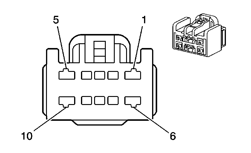
|
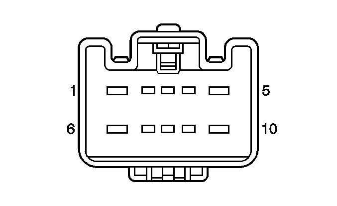
| ||||||||||||||
|---|---|---|---|---|---|---|---|---|---|---|---|---|---|---|---|
Connector Part Information |
| Connector Part Information |
| ||||||||||||
Pin | Wire Color | Circuit No. | Function | Pin | Wire Color | Circuit No. | Function | ||||||||
1 | RD/WH | 2040 | Battery Positive Voltage | 1 | RD/WH | 2040 | Battery Positive Voltage | ||||||||
2 | YE | 772 | Transmission Range Switch Signal B (M82) | 2 | YE | 772 | Transmission Range Switch Signal B (M82) | ||||||||
3 | GY | 773 | Transmission Range Switch Signal C (M82) | 3 | GY | 773 | Transmission Range Switch Signal C (M82) | ||||||||
4 | -- | -- | Not Used | 4 | -- | -- | Not Used | ||||||||
5 | PU/WH | 1382 | LED Dimming Signal (M82) | 5 | PU/WH | 1382 | LED Dimming Signal (M82) | ||||||||
6 | YE | 243 | Accessory Voltage (M82) | 6 | YE | 243 | Accessory Voltage (M82) | ||||||||
7 | WH | 776 | Transmission Range Switch Signal P (M82) | 7 | WH | 776 | Transmission Range Switch Signal P (M82) | ||||||||
8 | BK/WH | 771 | Transmission Range Switch Signal A (M82) | 8 | TN/WH | 771 | Transmission Range Switch Signal A (M82) | ||||||||
9 | -- | -- | Not Used | 9 | -- | -- | Not Used | ||||||||
10 | YE | 1491 | Backlight Lamps Control (M82) | 10 | YE | 1491 | Backlight Lamps Control (M82) | ||||||||
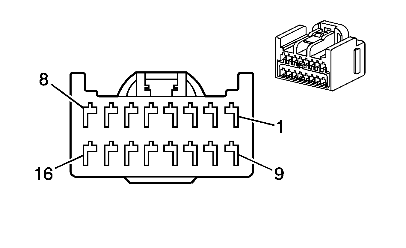
|
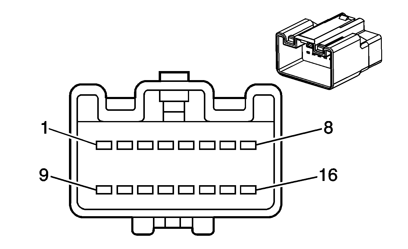
| ||||||||||||||
|---|---|---|---|---|---|---|---|---|---|---|---|---|---|---|---|
Connector Part Information |
| Connector Part Information |
| ||||||||||||
Pin | Wire Color | Circuit No. | Function | Pin | Wire Color | Circuit No. | Function | ||||||||
1 | RD/WH | 3640 | Battery Positive Voltage | 1 | RD/WH | 3640 | Battery Positive Voltage | ||||||||
2 | D-GN | 44 | Instrument Panel Lamps Dimmer Switch Signal | 2 | D-GN | 44 | Instrument Panel Lamps Dimmer Switch Signal | ||||||||
3 | BARE | 1489 | Drain Wire (U57) | 3 | BARE | 1489 | Drain Wire (U57) | ||||||||
4 | D-GN | 1488 | Noise Reduction Microphone Supply Voltage (U57) | 4 | D-GN | 1488 | Noise Reduction Microphone Supply Voltage (U57) | ||||||||
5 | PK/BK | 1597 | Courtesy Lamps Switch On Signal | 5 | PK/BK | 1597 | Courtesy Lamps Switch On Signal | ||||||||
6 | BARE | 1782 | Drain Wire (UE1) | 6 | BARE | 1782 | Drain Wire (UE1) | ||||||||
7 | GY | 655 | Cellular Microphone Signal (UE1) | 7 | GY | 655 | Cellular Microphone Signal (UE1) | ||||||||
8-9 | -- | -- | Not Used | 8-9 | -- | -- | Not Used | ||||||||
10 | PU | 1807 | Class 2 Serial Data | 10 | PU | 1807 | Class 2 Serial Data | ||||||||
11 | L-BU/BK | 1688 | 5-Volt Reference | 11 | L-BU/BK | 1688 | 5-Volt Reference | ||||||||
12 | YE | 5005 | Instrument Panel Lamps Dimmer Switch Low Reference | 12 | YE | 5005 | Instrument Panel Lamps Dimmer Switch Low Reference | ||||||||
13 | YE | 1491 | Backlight Lamps Control | 13 | YE | 1491 | Backlight Lamps Control | ||||||||
14 | PU | 5059 | Intrusion Sensor Alarm On Signal (Export w/UA6/UA2) | 14 | PU | 5059 | Intrusion Sensor Alarm On Signal (Export w/UA6/UA2) | ||||||||
15 | YE | 5058 | Intrusion Sensor Armed Signal (Export w/UA6/UA2) | 15 | YE | 5058 | Intrusion Sensor Armed Signal (Export w/UA6/UA2) | ||||||||
16 | PU | 679 | Radio Master Request Display Signal (UE1) | 16 | PU | 679 | Radio Master Request Display Signal (UE1) | ||||||||

|

| ||||||||||||||||||
|---|---|---|---|---|---|---|---|---|---|---|---|---|---|---|---|---|---|---|---|

| |||||||||||||||||||
Connector Part Information |
| Connector Part Information |
| ||||||||||||||||
Pin | Wire Color | Circuit No. | Function | Pin | Wire Color | Circuit No. | Function | ||||||||||||
A | BK | 2116 | Seat Belt Pretensioner - Front Passenger - High Control | A | L-GN | 2116 | Seat Belt Pretensioner - Front Passenger - High Control | ||||||||||||
B | -- | -- | Not Used | B | -- | -- | Not Used | ||||||||||||
C | WH | 2103 | Side Impact Module - Front Passenger - High Control | C | GY | 2103 | Side Impact Module - Front Passenger - High Control | ||||||||||||
D | D-GN | 2104 | Side Impact Module - Front Passenger - Low Control | D | D-BU | 2104 | Side Impact Module - Front Passenger - Low Control | ||||||||||||
E | -- | -- | Not Used | E | -- | -- | Not Used | ||||||||||||
F | WH | 2117 | Seat Belt Pretensioner - Front Passenger - Low Control | F | OG | 2117 | Seat Belt Pretensioner - Front Passenger - Low Control | ||||||||||||

|

| ||||||||||||||
|---|---|---|---|---|---|---|---|---|---|---|---|---|---|---|---|
Connector Part Information |
| Connector Part Information |
| ||||||||||||
Pin | Wire Color | Circuit No. | Function | Pin | Wire Color | Circuit No. | Function | ||||||||
1 | RD/WH | 3740 | Battery Positive Voltage (AH8) | 1 | OG | 3740 | Battery Positive Voltage (AH8) | ||||||||
2 | RD/WH | 2540 | Battery Positive Voltage (KA1) | 2 | OG | 2540 | Battery Positive Voltage (KA1) | ||||||||
3 | PK/BK | 1503 | Passenger Heated Seat High/Low Signal (KA1) | 3 | PK | 1503 | Passenger Heated Seat High/Low Signal (KA1) | ||||||||
4 | D-BU | 2181 | Passenger Heated Seat Control Module Status Signal (KA1) | 4 | L-BU/WH | 2181 | Passenger Heated Seat Control Module Status Signal (KA1) | ||||||||
5 | D-BU | 2307 | Passenger Air Bag On Indicator Control | 5 | D-BU | 2307 | Passenger Air Bag On Indicator Control | ||||||||
6 | D-GN | 2308 | Passenger Air Bag Off Indicator Control | 6 | D-GN | 2308 | Passenger Air Bag Off Indicator Control | ||||||||
7 | PK | 1139 | Ignition 1 Voltage | 7 | PK | 1139 | Ignition 1 Voltage | ||||||||
8 | -- | -- | Not Used | 8 | -- | -- | Not Used | ||||||||
9 | BN | 41 | Ignition 3 Voltage (KA1) | 9 | BN | 41 | Ignition 3 Voltage (KA1) | ||||||||
10 | BK/WH | 1751 | Ground | 10 | BK/WH | 1751 | Ground | ||||||||
11 | PK | 2306 | Occupant Sensor Signal | 11 | PK | 2306 | Occupant Sensor Signal | ||||||||
12 | PK | 5017 | Seat Belt Switch - Left - Low Reference | 12 | PK | 5017 | Seat Belt Switch - Left - Low Reference | ||||||||
13 | OG | 1362 | Seat belt Switch - Right -Signal | 13 | OG | 1362 | Seat belt Switch - Right -Signal | ||||||||
14 | BK | 550 | Ground (AH8/KA1) | 14 | BK | 550 | Ground (AH8/KA1) | ||||||||
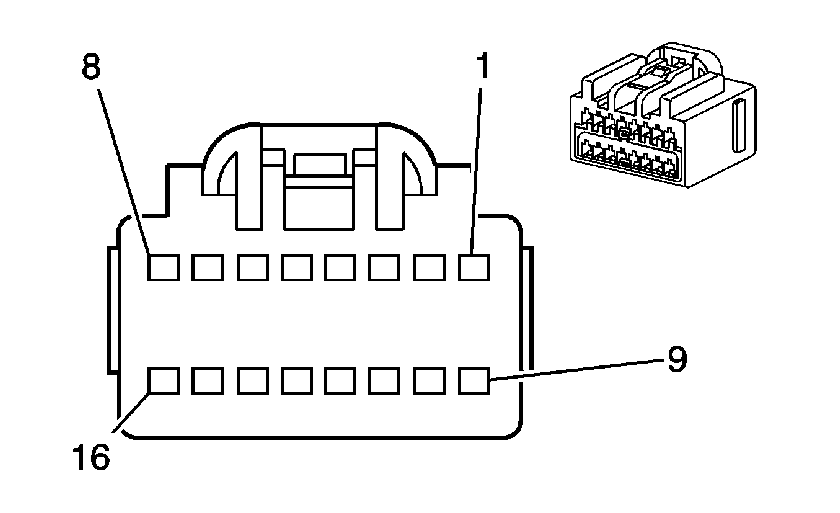
|
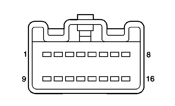
| ||||||||||||||
|---|---|---|---|---|---|---|---|---|---|---|---|---|---|---|---|
Connector Part Information |
| Connector Part Information |
| ||||||||||||
Pin | Wire Color | Circuit No. | Function | Pin | Wire Color | Circuit No. | Function | ||||||||
1 | D-BU/WH | 149 | Courtesy Lamp Supply Voltage | 1 | D-BU/WH | 149 | Courtesy Lamp Supply Voltage | ||||||||
2 | GY/BK | 1798 | Ground (UE1) | 2 | GY/BK | 1798 | Ground (UE1) | ||||||||
3 | PU | 1156 | Keypad Red LED Signal (UE1) | 3 | PU | 1156 | Keypad Red LED Signal (UE1) | ||||||||
4 | BN | 1941 | Ignition 3 Voltage (UE1) | 4 | BN | 1941 | Ignition 3 Voltage (UE1) | ||||||||
5 | -- | -- | Not Used | 5 | -- | -- | Not Used | ||||||||
6 | GY | 157 | Courtesy Lamp Control | 6 | GY | 157 | Courtesy Lamp Control | ||||||||
7 | BK | 850 | Ground | 7 | BK | 850 | Ground | ||||||||
8 | L-GN | 24 | Backup Lamp Supply Voltage (DD8) | 8 | L-GN | 24 | Backup Lamp Supply Voltage (DD8) | ||||||||
9 | PK | 1339 | Ignition 1 Voltage (DD8) | 9 | PK | 1339 | Ignition 1 Voltage (DD8) | ||||||||
10 | D-BU | 2307 | Passenger Air Bag ON Indicator Control | 10 | D-BU | 2307 | Passenger Air Bag ON Indicator Control | ||||||||
11 | D-GN | 2308 | Passenger Air Bag OFF Indicator Control | 11 | D-GN | 2308 | Passenger Air Bag OFF Indicator Control | ||||||||
12 | BK/WH | 851 | Ground (DD8) | 12 | BK/WH | 851 | Ground (DD8) | ||||||||
13 | TN | 1856 | Left Front Tweeter Speaker Output (+) | 13 | TN | 1856 | Left Front Tweeter Speaker Output (+) | ||||||||
14 | YE | 1956 | Left Front Tweeter Speaker Output (-) | 14 | YE | 1956 | Left Front Tweeter Speaker Output (-) | ||||||||
15 | L-GN | 1852 | Right Front Tweeter Speaker Output (+) | 15 | L-GN | 1852 | Right Front Tweeter Speaker Output (+) | ||||||||
16 | PU | 1952 | Right Front Tweeter Speaker Output (-) | 16 | PU | 1952 | Right Front Tweeter Speaker Output (-) | ||||||||
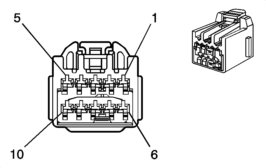
|
| ||||||||||||||
|---|---|---|---|---|---|---|---|---|---|---|---|---|---|---|---|
Connector Part Information |
| Connector Part Information |
| ||||||||||||
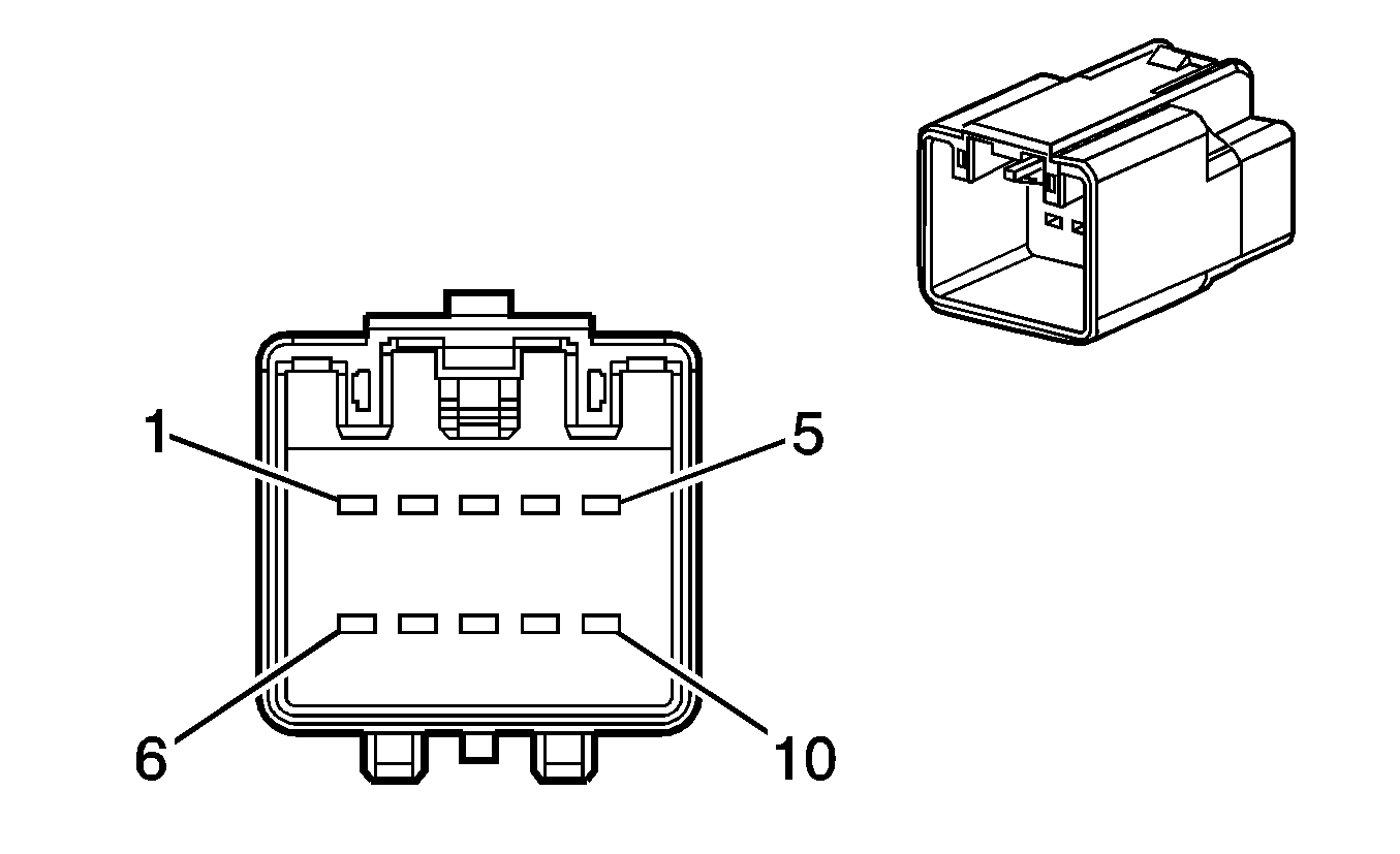
Pin | Wire Color | Circuit No. | Function | Pin | Wire Color | Circuit No. | Function | ||||||||
1 | D-BU | 128 | Sunroof Switch Low Reference | 1 | D-BU | 128 | Sunroof Switch Low Reference | ||||||||
2 | L-BU | 5027 | Sunroof Switch - Data 1 | 2 | L-BU | 5027 | Sunroof Switch - Data 1 | ||||||||
3 | BN | 5028 | Sunroof Switch - Data 2 | 3 | BN | 5028 | Sunroof Switch - Data 2 | ||||||||
4 | OG | 5029 | Sunroof Switch - Data 3 | 4 | OG | 5029 | Sunroof Switch - Data 3 | ||||||||
5 | PK | 5031 | Sunroof Switch - Data 5 | 5 | PK | 5031 | Sunroof Switch - Data 5 | ||||||||
6 | PU | 5032 | Sunroof Switch - Data 6 | 6 | PU | 5032 | Sunroof Switch - Data 6 | ||||||||
7 | TN | 5030 | Sunroof Switch - Data 4 | 7 | TN | 5030 | Sunroof Switch - Data 4 | ||||||||
8-10 | -- | -- | Not Used | 8-10 | -- | -- | Not Used | ||||||||
|
| ||||||||||||||
|---|---|---|---|---|---|---|---|---|---|---|---|---|---|---|---|
Connector Part Information |
| Connector Part Information |
| ||||||||||||
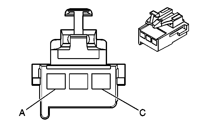
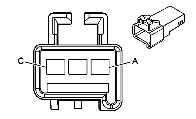
Pin | Wire Color | Circuit No. | Function | Pin | Wire Color | Circuit No. | Function | ||||||||
A | BK | 1050 | Ground (CF5) | A | BK | 1050 | Ground (CF5) | ||||||||
B | BN | 834 | Vehicle Speed Signal (CF5) | B | BN | 834 | Vehicle Speed Signal (CF5) | ||||||||
C | D-BU | 75 | RAP Relay Switch Supply Voltage (CF5) | C | D-BU | 75 | RAP Relay Switch Supply Voltage (CF5) | ||||||||
|
| ||||||||||||||
|---|---|---|---|---|---|---|---|---|---|---|---|---|---|---|---|
Connector Part Information |
| Connector Part Information |
| ||||||||||||
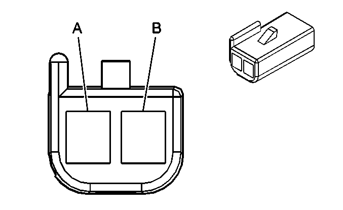
Pin | Wire Color | Circuit No. | Function | Pin | Wire Color | Circuit No. | Function | ||||||||
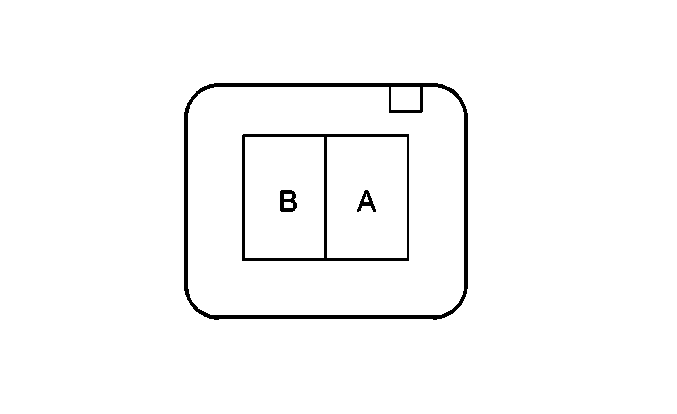
A | -- | -- | Not Used | A | -- | -- | Not Used | ||||||||
B | RD | 1486 | FM Composite Signal | B | OG | 1486 | FM Composite Signal | ||||||||

|

| ||||||||||||||
|---|---|---|---|---|---|---|---|---|---|---|---|---|---|---|---|
Connector Part Information |
| Connector Part Information |
| ||||||||||||
Pin | Wire Color | Circuit No. | Function | Pin | Wire Color | Circuit No. | Function | ||||||||
1 | BK | 450 | Ground | 1 | BK | 450 | Ground | ||||||||
2 | BK/WH | 451 | Ground (M82) | 2 | BK/WH | 451 | Ground (M82) | ||||||||
3 | L-GN | 5053 | Winter Mode Switch Signal (M82) | 3 | L-GN | 5053 | Winter Mode Switch Signal | ||||||||
4 | PU | 2056 | Auxiliary Video High Signal (U2Y/U2X) | 4 | PU | 2056 | Auxiliary Video High Signal (U2Y/U2X) | ||||||||
5 | -- | -- | Not Used | 5 | -- | -- | Not Used | ||||||||
6 | GY | 5054 | Sport Mode Switch Signal (M82) | 6 | GY | 5054 | Sport Mode Switch Signal (M82) | ||||||||
7 | BARE | 814 | Drain Wire (U2Y/U2X) | 7 | BARE | 814 | Drain Wire (U2Y/U2X) | ||||||||
8 | WH | 2058 | Auxiliary Audio Right Signal (U2Y/U2X) | 8 | WH | 2058 | Auxiliary Audio Right Signal (U2Y/U2X) | ||||||||
9 | YE | 2059 | Auxiliary Audio Left Signal (U2Y/U2X) | 9 | YE | 2059 | Auxiliary Audio Left Signal (U2Y/U2X) | ||||||||
10 | BARE | 814 | Drain Wire (U2Y/U2X) | 10 | BARE | 814 | Drain Wire (U2Y/U2X) | ||||||||

|

| ||||||||||||||
|---|---|---|---|---|---|---|---|---|---|---|---|---|---|---|---|
Connector Part Information |
| Connector Part Information |
| ||||||||||||
Pin | Wire Color | Circuit No. | Function | Pin | Wire Color | Circuit No. | Function | ||||||||
1 | D-BU | 1646 | Passenger Air Temperature Door Position | 1 | D-BU | 1646 | Passenger Air Temperature Door Position | ||||||||
2 | WH/BK | 1236 | Passenger Air Temperature Door Control B | 2 | WH/BK | 1236 | Passenger Air Temperature Door Control B | ||||||||
3 | GY/BK | 2778 | Passenger Air Temperature Door Control A | 3 | GY/BK | 2778 | Passenger Air Temperature Door Control A | ||||||||
4 | YE | 1318 | Mode Door Control B | 4 | PK | 1318 | Mode Door Control B | ||||||||
5 | YE/BK | 1814 | Lower Mode Door Position Signal | 5 | GY | 1814 | Lower Mode Door Position Signal | ||||||||
6 | TN | 2273 | Mode Door Control A | 6 | L-BU | 2273 | Mode Door Control A | ||||||||
7-9 | -- | -- | Not Used | 7-9 | -- | -- | Not Used | ||||||||
10 | GY | 705 | 5-Volt Reference | 10 | GY | 705 | 5-Volt Reference | ||||||||
11 | L-BU | 733 | Driver Air Temperature Door Position Signal | 11 | L-BU | 733 | Driver Air Temperature Door Position Signal | ||||||||
12 | YE | 1791 | Driver Air Temperature Door Control A | 12 | YE | 1791 | Driver Air Temperature Door Control A | ||||||||
13 | D-BU | 1199 | Driver Air Temperature Door Control B | 13 | D-BU | 1199 | Driver Air Temperature Door Control B | ||||||||
14 | YE | 61 | Low Reference | 14 | YE | 61 | Low Reference | ||||||||
15 | GY | 731 | Evaporator Temperature Sensor Signal | 15 | GY | 731 | Evaporator Temperature Sensor Signal | ||||||||
16 | -- | -- | Not Used | 16 | -- | -- | Not Used | ||||||||

|

| ||||||||||||||
|---|---|---|---|---|---|---|---|---|---|---|---|---|---|---|---|
Connector Part Information |
| Connector Part Information |
| ||||||||||||
Pin | Wire Color | Circuit No. | Function | Pin | Wire Color | Circuit No. | Function | ||||||||
1 | L-BU | 733 | Driver Air Temperature Door Position Signal | 1 | L-BU | 733 | Driver Air Temperature Door Position Signal | ||||||||
2 | D-BU | 1199 | Driver Air Temperature Door Control B | 2 | D-BU | 1199 | Driver Air Temperature Door Control B | ||||||||
3 | YE | 1791 | Driver Air Temperature Door Control A | 3 | YE | 1791 | Driver Air Temperature Door Control A | ||||||||
4 | YE | 1318 | Mode Door Control B | 4 | PK | 1318 | Mode Door Control B | ||||||||
5 | YE/BK | 1814 | Mode Door Position Signal | 5 | GY | 1814 | Mode Door Position Signal | ||||||||
6 | TN | 2273 | Mode Door Control A | 6 | L-BU | 2273 | Mode Door Control A | ||||||||
7-9 | -- | -- | Not Used | 7-9 | -- | -- | Not Used | ||||||||
10 | GY | 705 | 5-Volt Reference | 10 | GY | 705 | 5-Volt Reference | ||||||||
11 | D-BU | 1646 | Passenger Air Temperature Door Position Signal | 11 | D-BU | 1646 | Passenger Air Temperature Door Position Signal | ||||||||
12 | GY/BK | 2778 | Passenger Air Temperature Door Control A | 12 | GY/BK | 2778 | Passenger Air Temperature Door Control A | ||||||||
13 | WH/BK | 1236 | Passenger Air Temperature Door Control B | 13 | WH/BK | 1236 | Passenger Air Temperature Door Control B | ||||||||
14 | YE | 61 | Low Reference | 14 | YE | 61 | Low Reference | ||||||||
15 | GY | 731 | Evaporator Temperature Sensor Signal | 15 | GY | 731 | Evaporator Temperature Sensor Signal | ||||||||
16 | -- | -- | Not Used | 16 | -- | -- | Not Used | ||||||||

|

| ||||||||||||||
|---|---|---|---|---|---|---|---|---|---|---|---|---|---|---|---|
Connector Part Information |
| Connector Part Information |
| ||||||||||||
Pin | Wire Color | Circuit No. | Function | Pin | Wire Color | Circuit No. | Function | ||||||||
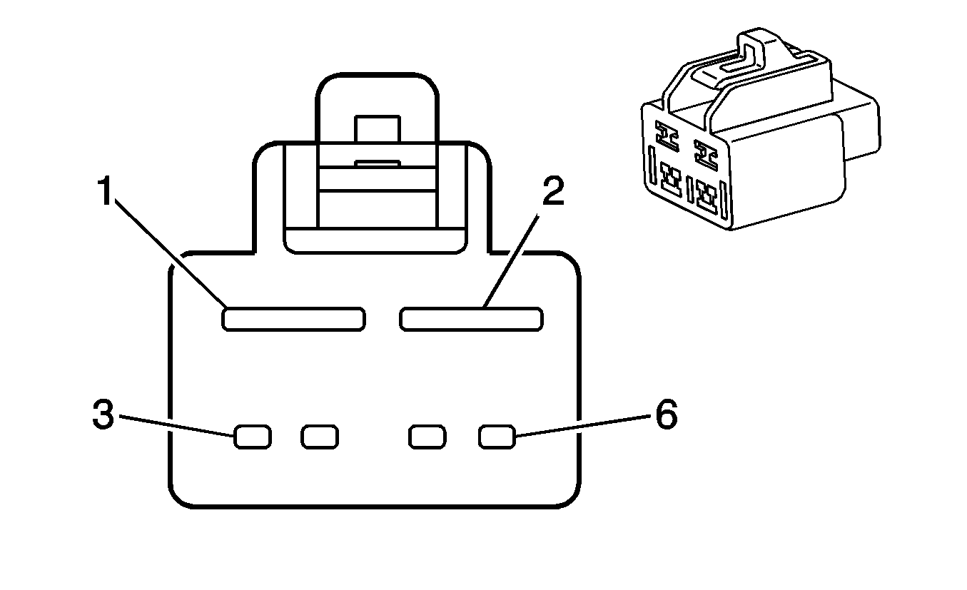
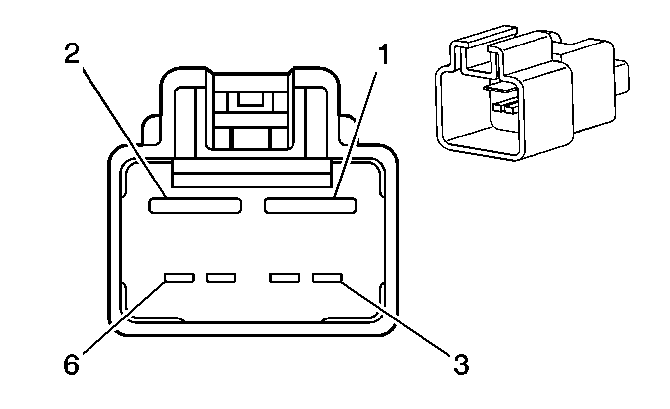
1 | L-GN/BK | 1794 | Left (U66) or Rear (U57) Subwoofer Speaker Output (-) | 1 | L-GN/BK | 1794 | Left (U66) or Rear (U57) Subwoofer Speaker Output (-) | ||||||||
2 | -- | -- | Not Used | 2 | -- | -- | Not Used | ||||||||
3 | OG/BK | 737 | Rear Compartment Lamp Control | 3 | OG/BK | 737 | Rear Compartment Lamp Control | ||||||||
4 | L-BU/BK | 315 | Right Subwoofer Speaker Output (-) (U66) | 4 | L-BU/BK | 315 | Right Subwoofer Speaker Output (-) (U66) | ||||||||
5 | D-BU/WH | 149 | Courtesy Lamp Supply Voltage | 5 | D-BU/WH | 149 | Courtesy Lamp Supply Voltage | ||||||||
6 | D-GN | 1795 | Right Subwoofer Speaker Output (+) (U66) | 6 | D-GN | 1795 | Right Subwoofer Speaker Output (+) (U66) | ||||||||
7 | D-BU/WH | 346 | Left (U66) or Rear (U57) Subwoofer Speaker Output (+) | 7 | D-BU/WH | 346 | Left (U66) or Rear (U57) Subwoofer Speaker Output (+) | ||||||||
8-14 | -- | -- | Not Used | 8-14 | -- | -- | Not Used | ||||||||
|
| ||||||||||||||
|---|---|---|---|---|---|---|---|---|---|---|---|---|---|---|---|
Connector Part Information |
| Connector Part Information |
| ||||||||||||
Pin | Wire Color | Circuit No. | Function | Pin | Wire Color | Circuit No. | Function | ||||||||
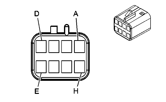
1 | L-BU | 188 | Blower Motor Control Processor Supply Voltage | 1 | L-BU | 188 | Blower Motor Control Processor Supply Voltage | ||||||||
2 | BK | 450 | Ground | 2 | BK | 450 | Ground | ||||||||
3 | BN | 41 | Ignition 3 Voltage | 3 | TN | 41 | Ignition 3 Voltage | ||||||||
4 | PU | 1838 | Recirculation Door Control A | 4 | PU | 1838 | Recirculation Door Control A | ||||||||
5 | D-GN | 1614 | Recirculation Door Control B | 5 | D-GN | 1614 | Recirculation Door Control B | ||||||||
6 | GY/BK | 754 | Blower Motor Speed Control | 6 | GY/BK | 754 | Blower Motor Speed Control | ||||||||
|
| ||||||||||||||
|---|---|---|---|---|---|---|---|---|---|---|---|---|---|---|---|
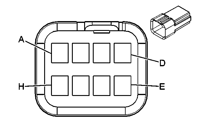
Connector Part Information |
| Connector Part Information |
| ||||||||||||
Pin | Wire Color | Circuit No. | Function | Pin | Wire Color | Circuit No. | Function | ||||||||
A | PU | 709 | Left Park Lamp Supply Voltage (w/o T79) | A | D-BU | 709 | Left Park Lamp Supply Voltage (w/o T79) | ||||||||
1472 | Left Park Lamp Supply Voltage (w/T79) | PU | 1472 | Left Park Lamp Supply Voltage (w/T79) | |||||||||||
B | WH | 17 | Stop Lamp Supply Voltage (w/o T79) | B | WH | 17 | Stop Lamp Supply Voltage (w/o T79) | ||||||||
-- | -- | Not Used (w/T79) | -- | -- | Not Used (w/T79) | ||||||||||
C | L-BU/WH | 1314 | Left Turn Signal Indicator Lamp Supply Voltage | C | L-BU/WH | 1314 | Left Turn Signal Indicator Lamp Supply Voltage | ||||||||
D | BK | 850 | Ground | D | BK | 850 | Ground | ||||||||
E | D-BU/WH | 1315 | Right Turn Signal Indicator Lamp Supply Voltage | E | -- | -- | Not Used | ||||||||
F | PU | 709 | Left Park Lamp Supply Voltage (w/o T79) | F | PU | 709 | Left Park Lamp Supply Voltage (w/o T79) | ||||||||
-- | -- | Not Used (w/T79) | -- | -- | Not Used (w/T79) | ||||||||||
G | WH | 17 | Stop Lamp Supply Voltage (w/T79) | G | WH/BK | 17 | Stop Lamp Supply Voltage | ||||||||
H | PU | 709 | Left Park Lamp Supply Voltage | H | OG | 709 | Left Park Lamp Supply Voltage | ||||||||

|

| ||||||||||||||
|---|---|---|---|---|---|---|---|---|---|---|---|---|---|---|---|
Connector Part Information |
| Connector Part Information |
| ||||||||||||
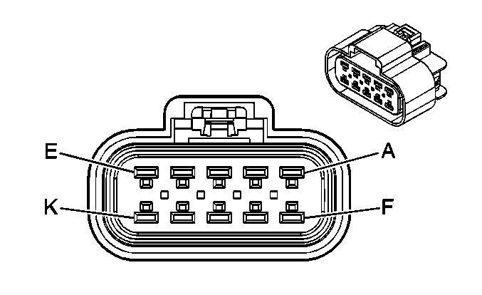
Pin | Wire Color | Circuit No. | Function | Pin | Wire Color | Circuit No. | Function | ||||||||
A | BN/WH | 309 | Right Park Lamp Supply Voltage (w/o T79) | A | D-BU | 1473 | Right Park Lamp Supply Voltage (w/o T79) | ||||||||
BN/WH | 1473 | Right Park Lamp Supply Voltage (w/T79) | BN/WH | 1473 | Right Park Lamp Supply Voltage (w/T79) | ||||||||||
B | WH | 17 | Stop Lamp Supply Voltage (w/o T79) | B | WH | 17 | Stop Lamp Supply Voltage (w/o T79) | ||||||||
-- | -- | Not Used (w/T79) | -- | -- | Not Used (w/T79) | ||||||||||
C | D-BU/WH | 1315 | Right Turn Signal Indicator Lamp Supply Voltage | C | L-BU/WH | 1315 | Right Turn Signal Indicator Lamp Supply Voltage | ||||||||
D | BK | 1050 | Ground | D | BK | 1050 | Ground | ||||||||
E | -- | -- | Not Used | E | -- | -- | Not Used | ||||||||
F | BN/WH | 309 | Right Park Lamp Supply Voltage (w/o T79) | F | PU | 309 | Right Park Lamp Supply Voltage (w/o T79) | ||||||||
-- | -- | Not Used (w/T79) | -- | -- | Not Used (w/T79) | ||||||||||
G | WH | 17 | Stop Lamp Supply Voltage (w/T79) | G | WH/BK | 17 | Stop Lamp Supply Voltage (w/T79) | ||||||||
H | BN/WH | 309 | Right Park Lamp Supply Voltage | H | OG | 1473 | Right Park Lamp Supply Voltage | ||||||||
|
| ||||||||||||||
|---|---|---|---|---|---|---|---|---|---|---|---|---|---|---|---|
Connector Part Information |
| Connector Part Information |
| ||||||||||||
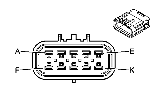
Pin | Wire Color | Circuit No. | Function | Pin | Wire Color | Circuit No. | Function | ||||||||
A | GY | 120 | Fuel Pump Supply Voltage | A | GY | 120 | Fuel Pump Supply Voltage | ||||||||
B | D-GN | 890 | Fuel Tank Pressure Sensor Signal | B | D-GN | 890 | Fuel Tank Pressure Sensor Signal | ||||||||
C | GY | 2709 | 5-Volt Reference | C | GY | 596 | 5-Volt Reference | ||||||||
D | WH | 1310 | EVAP Canister Vent Solenoid Control | D | WH | 1310 | EVAP Canister Vent Solenoid Control | ||||||||
E | TN | 2759 | Low Reference | E | TN | 452 | Low Reference | ||||||||
F | L-BU | 1937 | Fuel Level Sensor Signal - Primary | F | D-BU | 1936 | Fuel Level Sensor Signal - Primary | ||||||||
G | D-BU | 1936 | Fuel Level Sensor Signal - Secondary | G | L-BU | 1937 | Fuel Level Sensor Signal - Secondary | ||||||||
H | -- | -- | Not Used | H | -- | -- | Not Used | ||||||||
J | PK | 1539 | Battery Positive Voltage | J | RD/WH | 1540 | Battery Positive Voltage | ||||||||
K | BK | 1050 | Ground | K | BK | 1050 | Ground | ||||||||
|
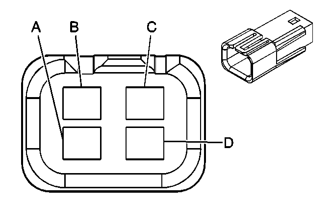
| ||||||||||||||
|---|---|---|---|---|---|---|---|---|---|---|---|---|---|---|---|
Connector Part Information |
| Connector Part Information |
| ||||||||||||
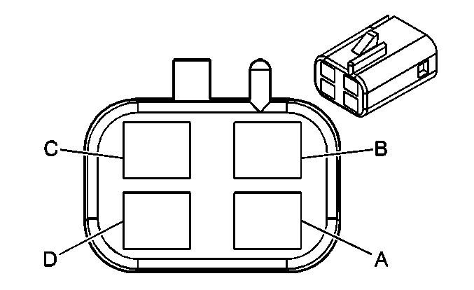
Pin | Wire Color | Circuit No. | Function | Pin | Wire Color | Circuit No. | Function | ||||||||
A | YE | 32 | Instrument Panel Lamp Fuse Supply Voltage 1 | A | YE | 32 | Instrument Panel Lamp Fuse Supply Voltage 1 | ||||||||
B | L-GN | 24 | Backup Lamp Supply Voltage | B | L-GN | 24 | Backup Lamp Supply Voltage | ||||||||
C | WH | 17 | Stop Lamp Supply Voltage | C | WH | 17 | Stop Lamp Supply Voltage | ||||||||
D | BK | 850 | Ground | D | BK | 850 | Ground | ||||||||
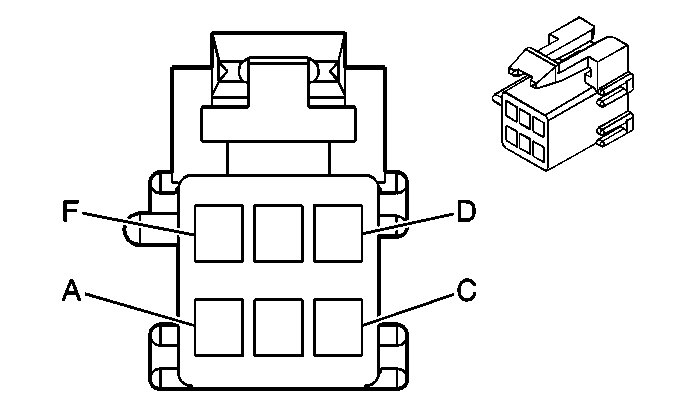
|
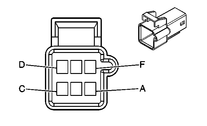
| ||||||||||||||
|---|---|---|---|---|---|---|---|---|---|---|---|---|---|---|---|
Connector Part Information |
| Connector Part Information |
| ||||||||||||
Pin | Wire Color | Circuit No. | Function | Pin | Wire Color | Circuit No. | Function | ||||||||
A | YE | 32 | Instrument Panel Lamp Fuse Supply Voltage 1 | A | YE | 32 | Instrument Panel Lamp Fuse Supply Voltage 1 | ||||||||
B | L-GN | 24 | Backup Lamp Supply Voltage | B | L-GN | 24 | Backup Lamp Supply Voltage | ||||||||
C | WH | 17 | Stop Lamp Supply Voltage | C | WH | 17 | Stop Lamp Supply Voltage | ||||||||
D | BK | 850 | Ground | D | BK | 850 | Ground | ||||||||
E | OG | 122 | Rear Fog Lamp Supply Voltage | E | OG | 122 | Rear Fog Lamp Supply Voltage | ||||||||
F | -- | -- | Not Used | F | -- | -- | Not Used | ||||||||

|

| ||||||||||||||
|---|---|---|---|---|---|---|---|---|---|---|---|---|---|---|---|
Connector Part Information |
| Connector Part Information |
| ||||||||||||
Pin | Wire Color | Circuit No. | Function | Pin | Wire Color | Circuit No. | Function | ||||||||
A | GY | 120 | Fuel Pump Supply Voltage | A | GY | 120 | Fuel Pump Supply Voltage | ||||||||
B | D-GN | 890 | Fuel Tank Pressure Sensor Signal | B | D-GN | 890 | Fuel Tank Pressure Sensor Signal | ||||||||
C | GY | 596 | 5-Volt Reference | C | GY | 2709 | 5-Volt Reference | ||||||||
D | WH | 1310 | EVAP Canister Vent Solenoid Control | D | WH | 1310 | EVAP Canister Vent Solenoid Control | ||||||||
E | TN | 452 | Low Reference | E | TN | 2759 | Low Reference | ||||||||
F | D-BU | 1936 | Fuel Level Sensor Signal - Primary | F | L-BU | 1936 | Fuel Level Sensor Signal - Primary | ||||||||
G | L-BU | 1937 | Fuel Level Sensor Signal - Secondary | G | D-BU | 1937 | Fuel Level Sensor Signal - Secondary | ||||||||
H | -- | -- | Not Used | H | -- | -- | Not Used | ||||||||
J | RD/WH | 1540 | Battery Positive Voltage | J | PK | 1540 | Battery Positive Voltage | ||||||||
K | BK | 1050 | Ground | K | BK | 1050 | Ground | ||||||||

|

| ||||||||||||||
|---|---|---|---|---|---|---|---|---|---|---|---|---|---|---|---|
Connector Part Information |
| Connector Part Information |
| ||||||||||||
Pin | Wire Color | Circuit No. | Function | Pin | Wire Color | Circuit No. | Function | ||||||||
1 | RD/WH | 1040 | Battery Positive Voltage | 1 | RD/WH | 1040 | Battery Positive Voltage | ||||||||
2 | RD/WH | 640 | Battery Positive Voltage | 2 | RD/WH | 640 | Battery Positive Voltage | ||||||||
3 | PU | 1807 | Class 2 Serial Data | 3 | PU | 1807 | Class 2 Serial Data | ||||||||
4-5 | -- | -- | Not Used | 4-5 | -- | -- | Not Used | ||||||||
6 | BK/WH | 351 | Ground | 6 | BK/WH | 351 | Ground | ||||||||
7 | BK | 350 | Ground | 7 | BK | 350 | Ground | ||||||||
8 | BK/WH | 351 | Ground | 8 | BK/WH | 351 | Ground | ||||||||
9 | L-BU | 1957 | Left Front Midrange Speaker Output (-) (w/U66) | 9 | L-BU | 1957 | Left Front Midrange Speaker Output (-) (w/U66) | ||||||||
TN | 1856 | Left Front Tweeter Speaker Output (+) (w/U57) | TN | 1856 | Left Front Tweeter Speaker Output (+) (w/U57) | ||||||||||
10 | D-BU | 1857 | Left Front Midrange Speaker Output (+) (w/U66) | 10 | D-BU | 1857 | Left Front Midrange Speaker Output (+) (w/U66) | ||||||||
YE | 1956 | Left Front Tweeter Speaker Output (-) (w/U57) | YE | 1956 | Left Front Tweeter Speaker Output (-) (w/U57) | ||||||||||
11 | D-BU/WH | 149 | Courtesy Lamp Supply Voltage | 11 | D-BU/WH | 149 | Courtesy Lamp Supply Voltage | ||||||||
12 | GY | 157 | Courtesy Lamp Control | 12 | GY | 157 | Courtesy Lamp Control | ||||||||
13-14 | -- | -- | Not Used | 13-14 | -- | -- | Not Used | ||||||||
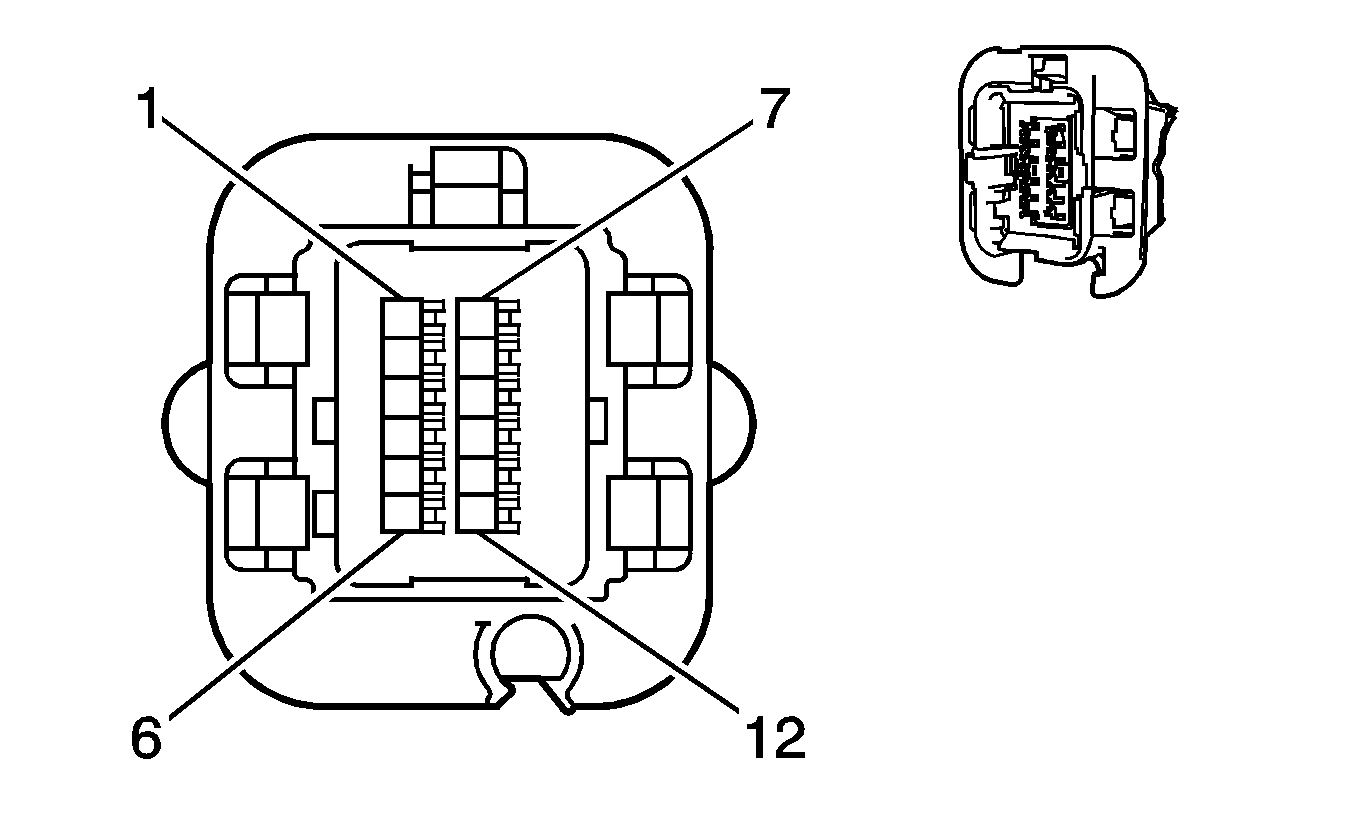
|
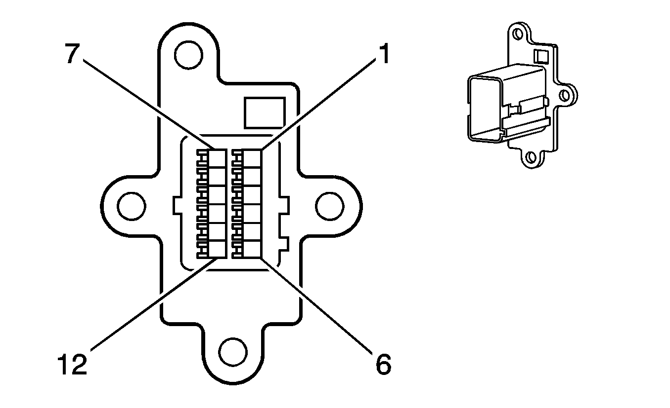
| ||||||||||||||
|---|---|---|---|---|---|---|---|---|---|---|---|---|---|---|---|
Connector Part Information |
| Connector Part Information |
| ||||||||||||
Pin | Wire Color | Circuit No. | Function | Pin | Wire Color | Circuit No. | Function | ||||||||
1 | YE | 1491 | Backlight Lamps Control | 1 | YE | 1491 | Backlight Lamps Control | ||||||||
2 | D-BU/WH | 149 | Courtesy Lamp Supply Voltage | 2 | D-BU/WH | 149 | Courtesy Lamp Supply Voltage | ||||||||
3 | GY | 157 | Courtesy Lamp Control | 3 | GY | 157 | Courtesy Lamp Control | ||||||||
4 | RD/WH | 640 | Battery Positive Voltage | 4 | RD/WH | 640 | Battery Positive Voltage | ||||||||
5 | PU | 1807 | Class 2 Serial Data | 5 | PU | 1807 | Class 2 Serial Data | ||||||||
6 | BK/WH | 351 | Ground | 6 | BK/WH | 351 | Ground | ||||||||
7-12 | -- | -- | Not Used | 7-12 | -- | -- | Not Used | ||||||||

|

| ||||||||||||||
|---|---|---|---|---|---|---|---|---|---|---|---|---|---|---|---|
Connector Part Information |
| Connector Part Information |
| ||||||||||||
Pin | Wire Color | Circuit No. | Function | Pin | Wire Color | Circuit No. | Function | ||||||||
1 | RD/WH | 1040 | Battery Positive Voltage | 1 | RD/WH | 1040 | Battery Positive Voltage | ||||||||
2 | RD/WH | 740 | Battery Positive Voltage | 2 | RD/WH | 740 | Battery Positive Voltage | ||||||||
3 | PU | 1807 | Class 2 Serial Data | 3 | PU | 1807 | Class 2 Serial Data | ||||||||
4 | BK/WH | 451 | Ground | 4 | BK/WH | 451 | Ground | ||||||||
5-7 | -- | -- | Not Used | 5-7 | -- | -- | Not Used | ||||||||
8 | D-GN | 1953 | Right Front Midrange Speaker Output (-) (w/U66) | 8 | D-GN | 1953 | Right Front Midrange Speaker Output (-) (w/U66) | ||||||||
PU | 1952 | Right Front Tweeter Speaker Output (-) (w/U57) | PU | 1952 | Right Front Tweeter Speaker Output (-) (w/U57) | ||||||||||
9 | OG | 1853 | Right Front Midrange Speaker Output (+) (w/U66) | 9 | OG | 1853 | Right Front Midrange Speaker Output (+) (w/U66) | ||||||||
L-GN | 1852 | Right Front Tweeter Speaker Output (+) (w/U57) | L-GN | 1852 | Right Front Tweeter Speaker Output (+) (w/U57) | ||||||||||
10 | D-BU/WH | 149 | Courtesy Lamp Supply Voltage | 10 | D-BU/WH | 149 | Courtesy Lamp Supply Voltage | ||||||||
11 | GY | 157 | Courtesy Lamp Control | 11 | GY | 157 | Courtesy Lamp Control | ||||||||
12-13 | -- | -- | Not Used | 12-13 | -- | -- | Not Used | ||||||||
14 | BK | 450 | Ground | 14 | BK | 450 | Ground | ||||||||

|

| ||||||||||||||
|---|---|---|---|---|---|---|---|---|---|---|---|---|---|---|---|
Connector Part Information |
| Connector Part Information |
| ||||||||||||
Pin | Wire Color | Circuit No. | Function | Pin | Wire Color | Circuit No. | Function | ||||||||
1 | YE | 1491 | Backlight Lamps Control | 1 | YE | 1491 | Backlight Lamps Control | ||||||||
2 | OG | 1189 | Power Window Switch Front Passenger Down Signal | 2 | BN | 5295 | Power Window Switch Front Passenger Down Signal | ||||||||
3 | PU | 2765 | Power Window Switch Front Passenger Express Signal | 3 | PU | 2765 | Power Window Switch Front Passenger Express Signal | ||||||||
4 | D-GN | 1184 | Power Window Switch Front Passenger Up Signal | 4 | D-GN | 1184 | Power Window Switch Front Passenger Up Signal | ||||||||
5 | BK/WH | 451 | Ground | 5 | BK/WH | 451 | Ground | ||||||||
6 | L-BU | 244 | Passenger Door Lock Switch Lock Signal | 6 | L-BU | 244 | Passenger Door Lock Switch Lock Signal | ||||||||
7 | D-BU | 245 | Passenger Door Lock Switch Unlock Signal | 7 | D-BU | 245 | Passenger Door Lock Switch Unlock Signal | ||||||||
8 | D-BU/WH | 149 | Courtesy Lamp Supply Voltage | 8 | D-BU/WH | 149 | Courtesy Lamp Supply Voltage | ||||||||
9 | GY | 157 | Courtesy Lamp Control | 9 | GY | 157 | Courtesy Lamp Control | ||||||||
10-12 | -- | -- | Not Used | 10-12 | -- | -- | Not Used | ||||||||

|

| ||||||||||||||
|---|---|---|---|---|---|---|---|---|---|---|---|---|---|---|---|
Connector Part Information |
| Connector Part Information |
| ||||||||||||
Pin | Wire Color | Circuit No. | Function | Pin | Wire Color | Circuit No. | Function | ||||||||
1 | RD/WH | 1040 | Battery Positive Voltage | 1 | RD/WH | 1040 | Battery Positive Voltage | ||||||||
2 | RD/WH | 840 | Battery Positive Voltage | 2 | RD/WH | 840 | Battery Positive Voltage | ||||||||
3 | PU | 1807 | Class 2 Serial Data | 3 | PU | 1807 | Class 2 Serial Data | ||||||||
4 | BK/WH | 351 | Ground | 4 | BK/WH | 351 | Ground | ||||||||
5 | TN | 1859 | Left Rear Midrange Speaker Output (+) | 5 | TN | 1859 | Left Rear Midrange Speaker Output (+) | ||||||||
6 | WH | 1959 | Left Rear Midrange Speaker Output (-) | 6 | WH | 1959 | Left Rear Midrange Speaker Output (-) | ||||||||
7 | BK | 350 | Ground | 7 | BK | 350 | Ground | ||||||||
8-14 | -- | -- | Not Used | 8-14 | -- | -- | Not Used | ||||||||

|

| ||||||||||||||
|---|---|---|---|---|---|---|---|---|---|---|---|---|---|---|---|
Connector Part Information |
| Connector Part Information |
| ||||||||||||
Pin | Wire Color | Circuit No. | Function | Pin | Wire Color | Circuit No. | Function | ||||||||
1 | YE | 1491 | Backlight Lamps Control | 1 | YE | 1491 | Backlight Lamps Control | ||||||||
2 | YE | 1187 | Power Window Switch Left Rear Down Signal | 2 | YE | 1187 | Power Window Switch Left Rear Down Signal | ||||||||
3 | WH | 1185 | Power Window Switch Left Rear Up Signal | 3 | WH | 1185 | Power Window Switch Left Rear Up Signal | ||||||||
4 | BK/WH | 351 | Ground | 4 | BK/WH | 351 | Ground | ||||||||
5 | L-GN | 5048 | Power Window Switch Left Rear Express Signal | 5 | L-GN | 5048 | Power Window Switch Left Rear Express Signal | ||||||||
6 | TN | 1859 | Left Rear Midrange Speaker Output (+) | 6 | TN | 1859 | Left Rear Midrange Speaker Output (+) | ||||||||
7 | WH | 1959 | Left Rear Midrange Speaker Output (-) | 7 | WH | 1959 | Left Rear Midrange Speaker Output (-) | ||||||||
8-12 | -- | -- | Not Used | 8-12 | -- | -- | Not Used | ||||||||

|

| ||||||||||||||
|---|---|---|---|---|---|---|---|---|---|---|---|---|---|---|---|
Connector Part Information |
| Connector Part Information |
| ||||||||||||
Pin | Wire Color | Circuit No. | Function | Pin | Wire Color | Circuit No. | Function | ||||||||
1 | RD/WH | 1040 | Battery Positive Voltage | 1 | RD/WH | 1040 | Battery Positive Voltage | ||||||||
2 | RD/WH | 840 | Battery Positive Voltage | 2 | RD/WH | 840 | Battery Positive Voltage | ||||||||
3 | PU | 1807 | Class 2 Serial Data | 3 | PU | 1807 | Class 2 Serial Data | ||||||||
4 | BK/WH | 451 | Ground | 4 | BK/WH | 451 | Ground | ||||||||
5 | TN | 1855 | Right Rear Midrange Speaker Output (+) | 5 | TN | 1855 | Right Rear Midrange Speaker Output (+) | ||||||||
6 | OG | 1955 | Right Rear Midrange Speaker Output (-) | 6 | OG | 1955 | Right Rear Midrange Speaker Output (-) | ||||||||
7 | BK | 450 | Ground | 7 | BK | 450 | Ground | ||||||||
8-14 | -- | -- | Not Used | 8-14 | -- | -- | Not Used | ||||||||

|

| ||||||||||||||
|---|---|---|---|---|---|---|---|---|---|---|---|---|---|---|---|
Connector Part Information |
| Connector Part Information |
| ||||||||||||
Pin | Wire Color | Circuit No. | Function | Pin | Wire Color | Circuit No. | Function | ||||||||
1 | YE | 1491 | Backlight Lamps Control | 1 | YE | 1491 | Backlight Lamps Control | ||||||||
2 | D-GN | 1188 | Power Window Switch Right Rear Down Signal | 2 | D-GN | 1188 | Power Window Switch Right Rear Down Signal | ||||||||
3 | GY | 1186 | Power Window Switch Right Rear Up Signal | 3 | GY | 1186 | Power Window Switch Right Rear Up Signal | ||||||||
4 | BK/WH | 451 | Ground | 4 | BK/WH | 451 | Ground | ||||||||
5 | L-GN | 5049 | Power Window Switch Right Rear Express Signal | 5 | L-GN | 5049 | Power Window Switch Right Rear Express Signal | ||||||||
6 | TN | 1855 | Right Rear Midrange Speaker Output (+) | 6 | TN | 1855 | Right Rear Midrange Speaker Output (+) | ||||||||
7 | OG | 1955 | Right Rear Midrange Speaker Output (-) | 7 | OG | 1955 | Right Rear Midrange Speaker Output (-) | ||||||||
8-12 | -- | -- | Not Used | 8-12 | -- | -- | Not Used | ||||||||
