Steering Gear Replacement w/LHD
Tools Required
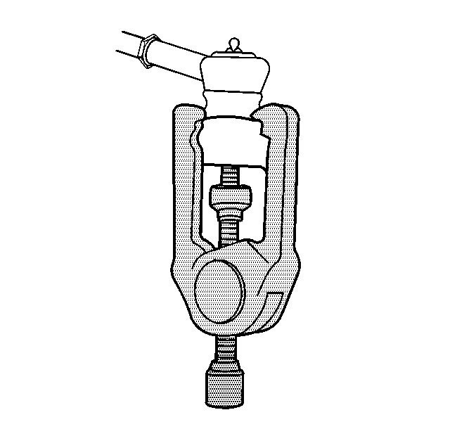
| • | J 24319-B Steering Linkage and Tie Rod Puller |
| • | J 42640 Steering Column Anti-Rotation Pin |
Removal Procedure
- Install the J 42640 to the steering column.
- Remove the front tires and wheels. Refer to Tire and Wheel Removal and Installation in Tires and Wheels.
- Remove the front air deflector. Refer to Front Air Deflector Replacement in Body Front End.
- Remove the intermediate shaft lower pinch bolt.
- Disconnect the intermediate shaft from the power steering gear.
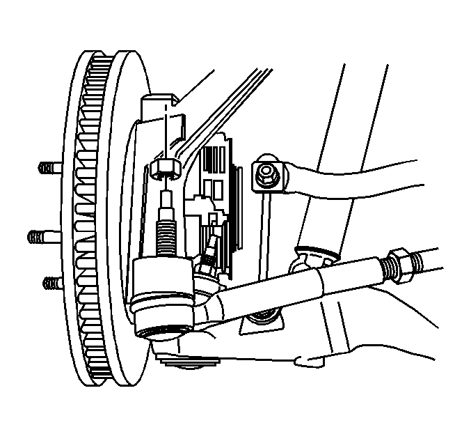
- Remove the outer tie rod nuts.
- Using the J 24319-B separate the outer tie rod from the steering knuckles.
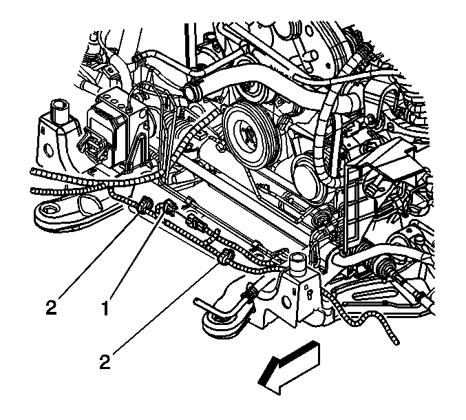
- If necessary, disconnect the variable effort steering electrical connector (1) from the power steering gear.
- Remove the stabilizer shaft. Refer to Stabilizer Shaft Replacement in Front Suspension.
- Place a drain pan under the vehicle.
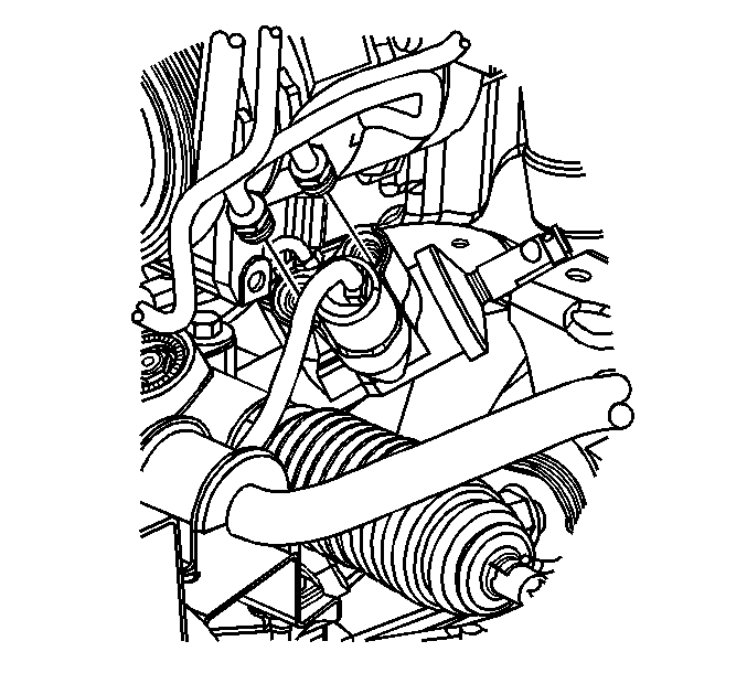
- Disconnect the power steering gear pressure and return lines from the power steering gear.
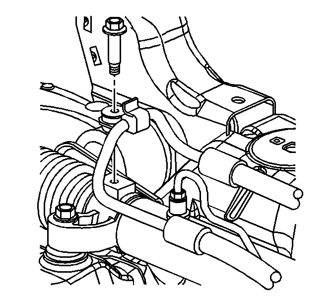
- Remove the power steering pressure line retainer bolt from the power steering gear.
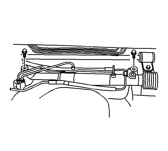
- Remove the power steering gear bolts.
- Remove the power steering gear through the left wheel opening.
- Transfer the outer tie rods if replacing the power steering gear.
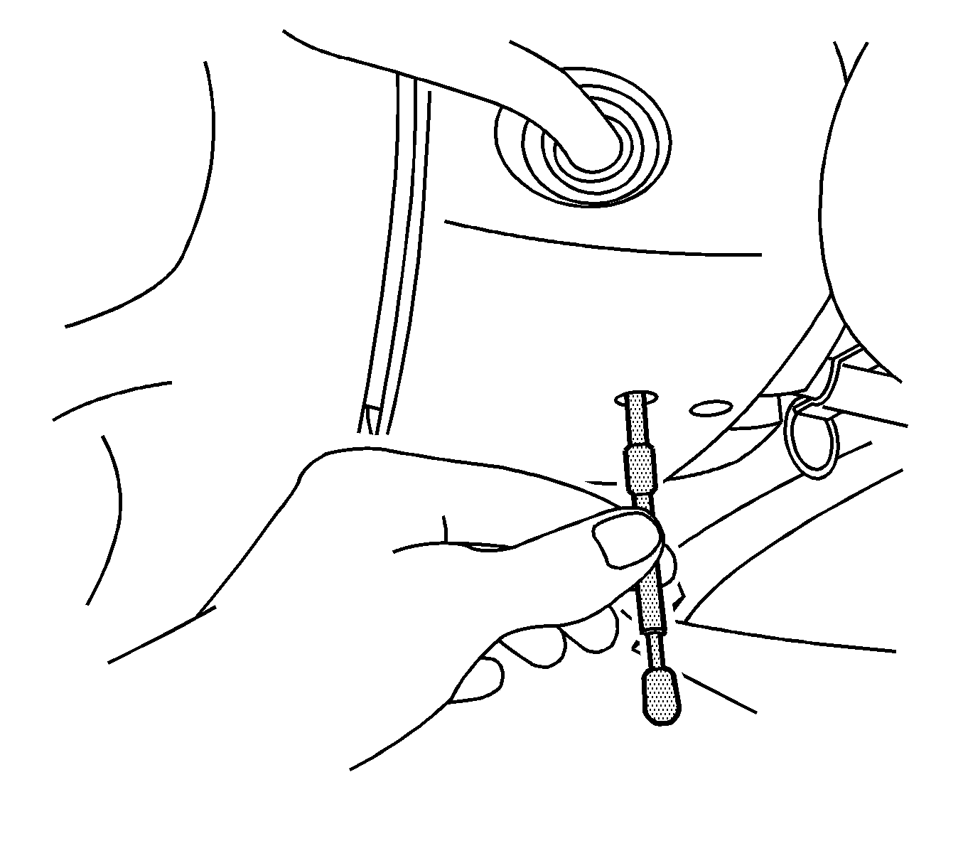
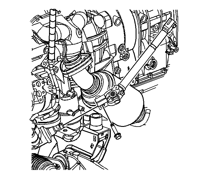
Caution: Failure to disconnect the intermediate shaft from the rack and pinion stub shaft can result in damage to the steering gear and/or intermediate shaft. This damage can cause loss of steering control which could result in personal injury.
Notice: The wheels of the vehicle must be straight ahead and the steering column in the LOCK position before disconnecting the steering column or intermediate shaft from the steering gear. Failure to do so will cause the coil assembly in the steering column to become uncentered which will cause damage to the coil assembly.
Installation Procedure
- Install the power steering gear through the left wheel opening.
- Install the power steering gear bolts.
- Install the power steering pressure line retainer bolt to the steering gear.
- Install the stabilizer shaft. Refer to Stabilizer Shaft Replacement in Front Suspension.
- Connect the power steering gear pressure and return lines to the power steering gear.
- If necessary, connect the variable effort steering electrical connector (1).
- Install the outer tie rod end to the steering knuckles.
- Install the outer tie rod nuts.
- Connect the intermediate shaft to the power steering gear.
- Install the intermediate shaft lower pinch bolt.
- Install the front air deflector. Refer to Front Air Deflector Replacement in Body Front End.
- Install the tire and wheels. Refer to Tire and Wheel Removal and Installation in Tires and Wheels.
- Remove the J 42640 from the steering column.
- Bleed the power steering system. Refer to Power Steering System Bleeding .
- Adjust the front toe. Refer to Front Toe Adjustment .
Notice: Refer to Fastener Notice in the Preface section.

Tighten
Tighten the bolts to 95 N·m (70 lb ft).

Tighten
Tighten the bolt to 9 N·m (80 lb in).

Important: Install new seals on the power steering pressure and return lines.
Tighten
Tighten the fittings to 30 N·m (22 lb ft).


Tighten
Tighten the nuts to 70 N·m (52 lb ft).

Tighten
Tighten the bolt to 50 N·m (37 lb ft).

Steering Gear Replacement w/RHD
Tools Required
| • | J 24319-B Steering Linkage and Tie Rod Puller |
| • | J 42640 Steering Column Anti-Rotation Pin |
Removal Procedure
- Install the J 42640 to the steering column.
- Remove the front tires and wheels. Refer to Tire and Wheel Removal and Installation in Tires and Wheels.
- Remove the front air deflector. Refer to Front Air Deflector Replacement in Body Front End.
- Remove the intermediate shaft lower pinch bolt.
- Disconnect the intermediate shaft from the power steering gear.
- Remove the outer tie rod nuts.
- Using the J 24319-B separate the outer tie rod from the steering knuckles.
- If necessary, disconnect the variable effort steering electrical connector (1) from the power steering gear.
- Remove the stabilizer shaft. Refer to Stabilizer Shaft Replacement in Front Suspension.
- Place a drain pan under the vehicle.
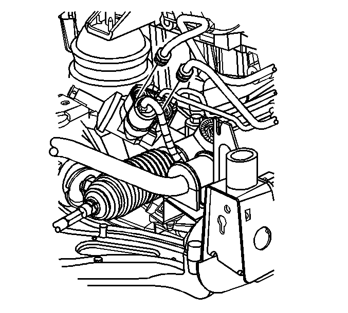
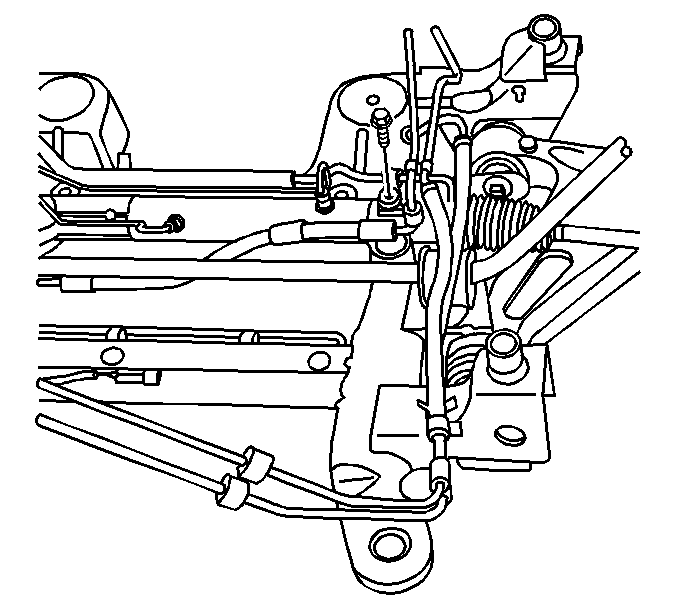
- Disconnect the power steering gear pressure and return lines from the power steering gear.
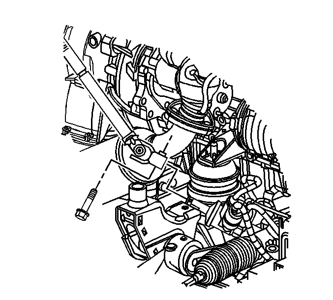
- Remove the power steering return line retainer bolt from the power steering gear.
- Remove the power steering gear bolts.
- Remove the power steering gear through the right wheel opening.
- Transfer the outer tie rods if replacing the power steering gear.

Caution: Failure to disconnect the intermediate shaft from the rack and pinion stub shaft can result in damage to the steering gear and/or intermediate shaft. This damage can cause loss of steering control which could result in personal injury.
Notice: The wheels of the vehicle must be straight ahead and the steering column in the LOCK position before disconnecting the steering column or intermediate shaft from the steering gear. Failure to do so will cause the coil assembly in the steering column to become uncentered which will cause damage to the coil assembly.



Installation Procedure
- Install the power steering gear through the left wheel opening.
- Install the power steering gear bolts.
- Install the power steering return line retainer bolt to the steering gear.
- Install the stabilizer shaft. Refer to Stabilizer Shaft Replacement in Front Suspension.
- Connect the power steering gear pressure and return lines to the power steering gear.
- If necessary, connect the variable effort steering electrical connector (1).
- Install the outer tie rod end to the steering knuckles.
- Install the outer tie rods nuts.
- Connect the intermediate shaft to the power steering gear.
- Install the intermediate shaft lower pinch bolt.
- Install the front air deflector. Refer to Front Air Deflector Replacement in Body Front End.
- Install the tire and wheels. Refer to Tire and Wheel Removal and Installation in Tires and Wheels.
- Remove the J 42640 from the steering column.
- Bleed the power steering system. Refer to Power Steering System Bleeding .
- Adjust the front toe. Refer to Front Toe Adjustment .
Notice: Refer to Fastener Notice in the Preface section.

Tighten
Tighten the bolts to 95 N·m (70 lb ft).

Tighten
Tighten the bolt to 9 N·m (80 lb in).

Important: Install new seals on the power steering pressure and return lines.
Tighten
Tighten the fittings to 30 N·m (22 lb ft).


Tighten
Tighten the nuts to 70 N·m (52 lb ft).

Tighten
Tighten the bolt to 50 N·m (37 lb ft).

