Controlling Rear Axle or Wheel Hop on Full-Throttle Application from a Standstill and/or Full Throttle 1-2 Shift (Install Supplementary Rear Sub-Frame Bushings)

| Subject: | Controlling Rear Axle or Wheel Hop on Full-Throttle Application From a Standstill and/or Full-Throttle 1-2 Shift (Install Supplementary Rear Sub-Frame Bushings) |
| Models: | 2004-2005 Cadillac CTS-V |
| Attention: | The information presented in this bulletin is intended to inform, educate, and provide an effective means to further improve the outstanding high-performace handling qualities of the CTS-V for customers who value very aggressive driving capabilities. |
This bulletin is being revised to expand the title line, include additional information, and add a repair procedure. Please discard Corporate Bulletin Number 05-04-114-001 (Section 04 - Driveline/Axle).
Condition
Some customers may comment on rear wheel hop or rear suspension bounce under full throttle acceleration. This condition is not unsafe by itself and is the result of very aggressive driving practices. This condition is primarily confined to hard acceleration from a standstill with wide open throttle, though it may be possible to induce if the customer attempts a hurried wide open throttle or "Power-Shift" from 1st to 2nd gear.
Notice: Vehicle component durability is greatly influenced by these driver abuses. Driving in this manner is not recommended.
Customer Expectations and Real World Usage
The CTS-V is a very high performance vehicle capable of class-leading acceleration that, in most cases, exceeds even the capabilities of pure sport and muscle cars. The 5.7L V8 engine in the CTS-V provides outstanding reserves of power. This large available engine torque, coupled with a suspension system and tire combination designed for maximum road adhesion, may result in wheel hop under certain conditions.
Cause
In the rear of the CTS-V, a sub-frame is mounted to the body structure at four rubber-isolated points. These mounts were carefully chosen to achieve an effective combination of excellent handling, while retaining effective damping of road shocks and bumps. The force of the suspension rapidly occillating vertically (hopping) provides enough weight transfer (up and down) that these bushings, which normally compress to help isolate passengers from irregular road surfaces, may deflect or compress in sympathy to wheel hop.
Correction
Improving High Performance Suspension Characteristics
For customers who value very aggressive driving capabilities, a revised set of firmer rear sub-frame bushings are available that may provide an incremental improvement in reducing the tendency of the rear suspension to wheel hop. This is an improvement that will further extend the handling capabilities of the CTS-V - it will not remove the possibility of wheel hop in all situations.
Important: Do NOT replace the rear sub-frame bushings unless the customer specifically has the concern of objectionable wheel hop.
Service Procedure
Use the following procedure to install the service rear frame supplemental bushings.
- Raise and suitably support the vehicle.
- Remove the left and right rear tire assemblies.
- Support the right rear lower control arm with a stand.
- Remove the lower shock absorber mounting bolt.
- Gradually lower the stand until the control arm is hanging.
- Remove the stand and use to support the left rear lower control arm.
- Remove the lower shock absorber mounting bolt.
- Gradually lower the stand until the control arm is hanging.
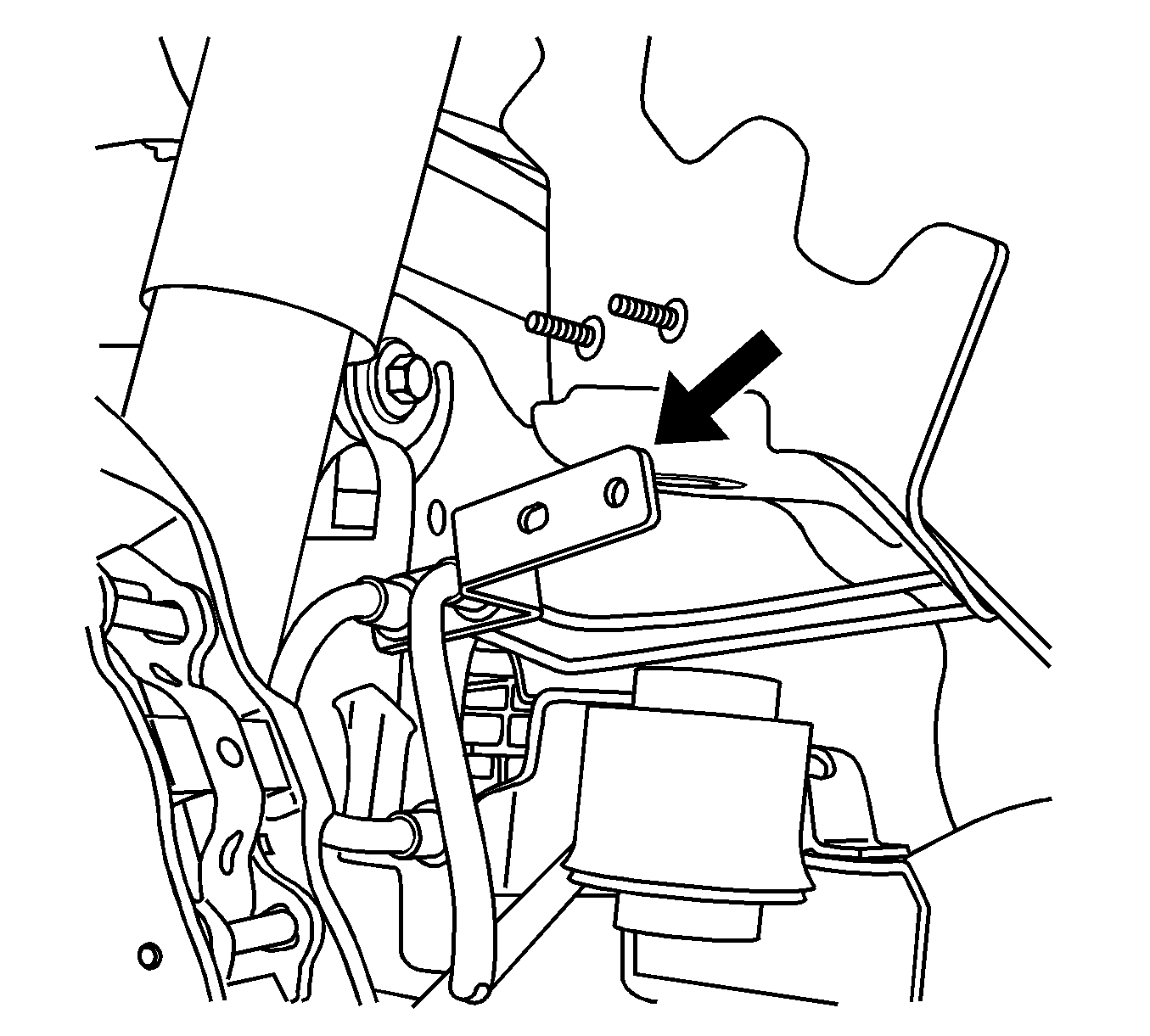
- Remove the brake pipe mounting bracket from the right side wheel well area.
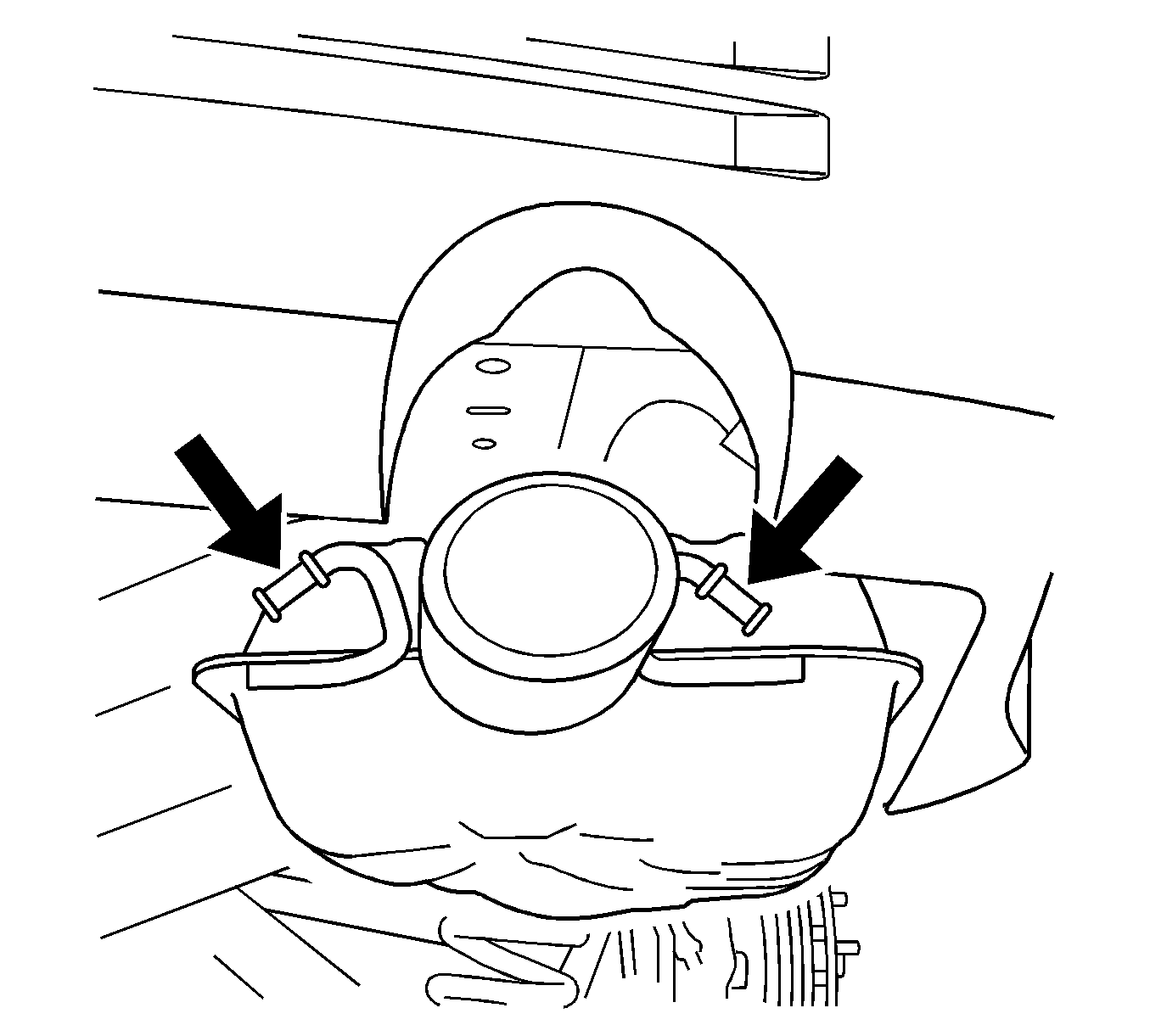
- Remove the right and left side exhausts from the hangers nearest the rear fascia.
- Install jacks and suitably support the rear frame.
- Remove the 4 rear frame attachment bolts.
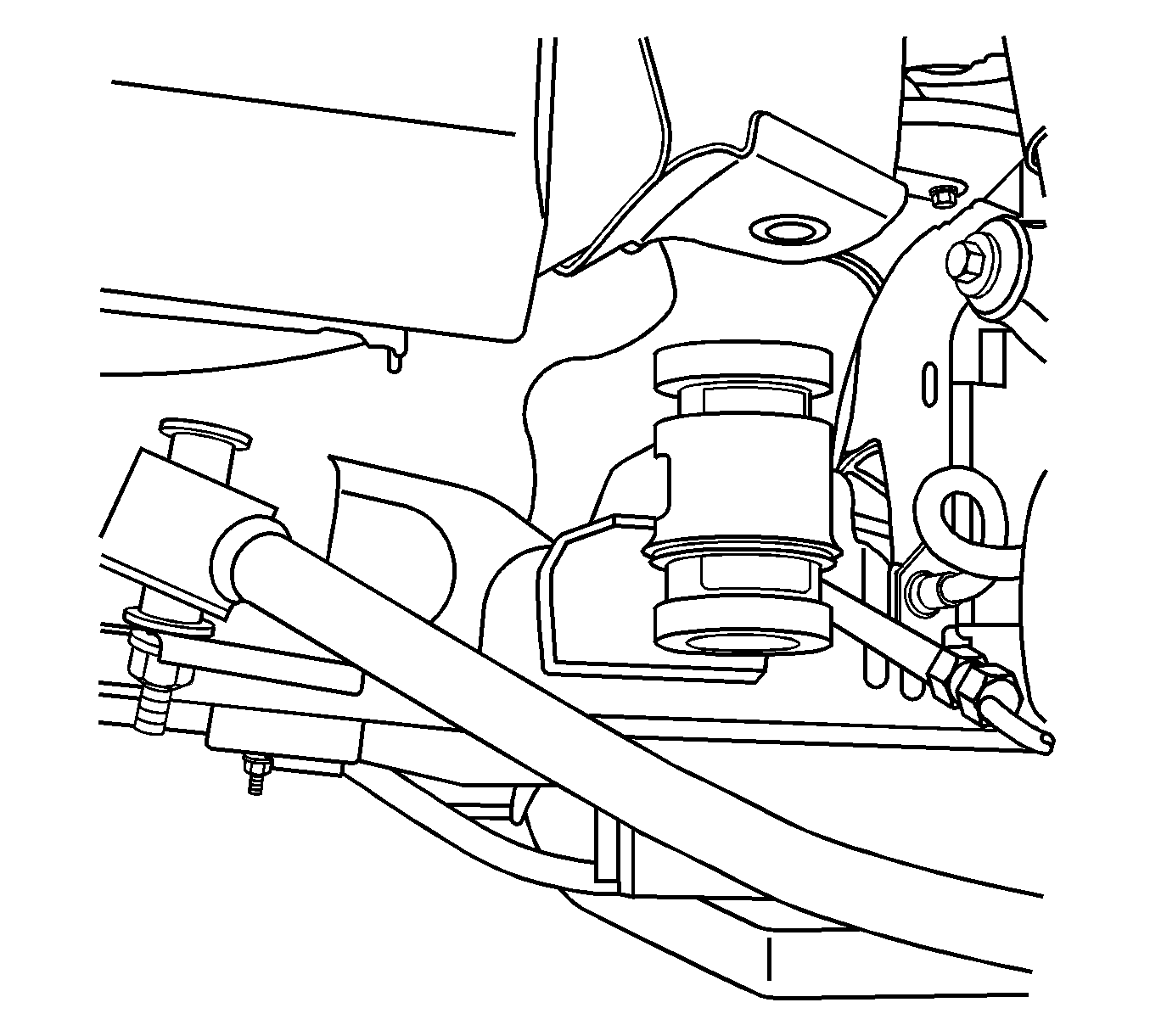
- The rear frame mounting points have reverse cone shaped locators as an integral part of the location. Lower the rear frame to obtain sufficient clearance to install the revised insulators.
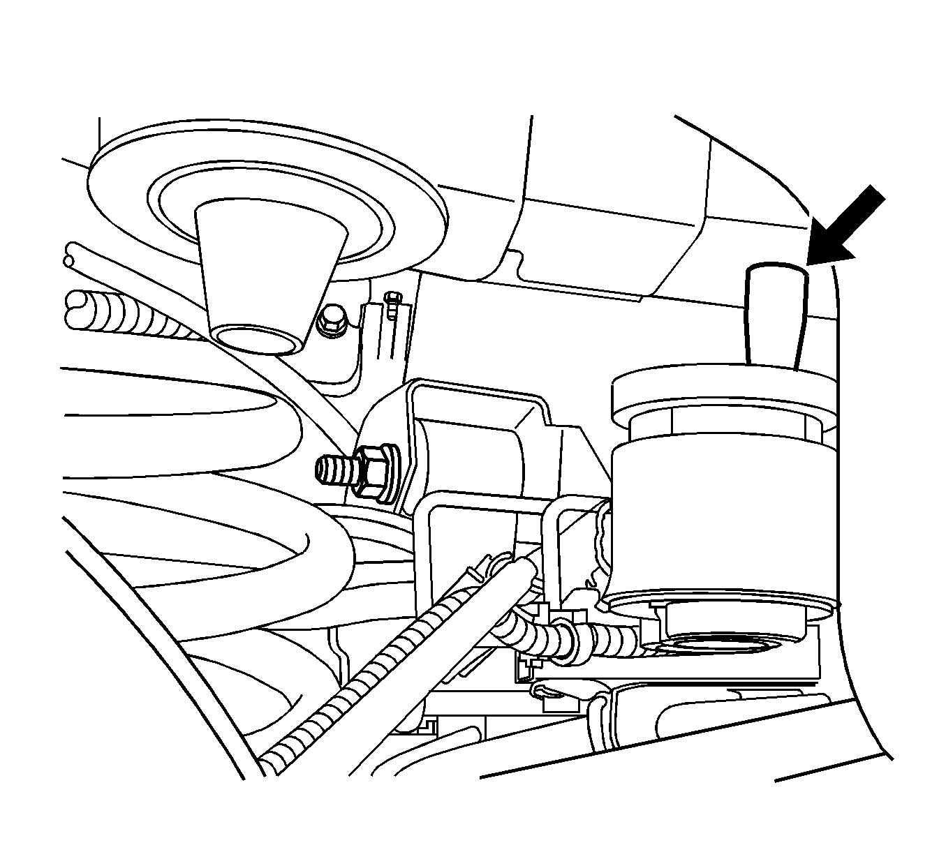
- The new bushings are installed over the existing bushings by inserting them into the voids of the original bushings. The front and rear frame bushings are different diameters but each matching half is the same and will only fit the proper locations. Install the new bushings to the frame mounts as shown in the illustration.
- Raise the frame making sure that the locating pegs are positioned properly and guide the frame to the correct position.
- Install the rear frame bolts.
- Remove the supports from the rear frame.
- Support and slightly raise the left lower control arm.
- Install the left shock absorber bolt to the lower control arm then remove the support.
- Support and slightly raise the right lower control arm.
- Install the right shock absorber bolt to the lower control arm then remove the support.
- Install the left wheel and tire assembly.
- Install the right wheel and tire assembly.
- Lower the vehicle.


Important: Only lower the rear frame enough to install the new bushings. The above steps include removal of components sufficient to lower the frame enough to complete this operation. Additional lowering of the frame may cause stress or damage to other components.

Caution: When raising the frame back to the vehicle, you will need to guide the coil springs back to their original mounted location points. Raising the frame back to the vehicle underbody will retention the springs. Failure to properly locate the springs upon re-installation of the frame may cause personal injury or damage to the vehicle.
Parts Information
Part Number | Description |
|---|---|
19133557 | Kit, Rear Supplemental Frame Bushings |
Parts are expected to be available for dealer ordering on July 28, 2005.
Warranty Information
For vehicles repaired under warranty, use:
Labor Operation | Description | Labor Time |
|---|---|---|
H9711* | Frame, Rear Supplemental Bushings -- Install | 0.7 hr |
E4010 | Toe, Rear Adjust | Use Published Labor Operation Time |
*This labor operation is intended for bulletin use only. It will not be published in the Labor Time Guide. | ||
