Engine Mount Bracket Replacement - Left Side RWD
Removal Procedure
Notice: Secure the steering wheel utilizing a strap to prevent rotation. Locking of the steering column will prevent damage and a possible malfunction of the SIR system. The steering wheel must be secured
in position before disconnecting the following components:
• The steering column • The intermediate shaft • The steering gear
- Remove the tower brace. Refer to Cross Vehicle Brace Replacement.
- Secure the steering wheel in place.
- Remove the lower section of the steering intermediate shaft. Refer to Lower Intermediate Steering Shaft Replacement.
- Remove the left and right lower engine mount nuts.
- Install a screw jack with a block of wood under the oil pan for support.
- Support the rear of the front frame with a screw jack.
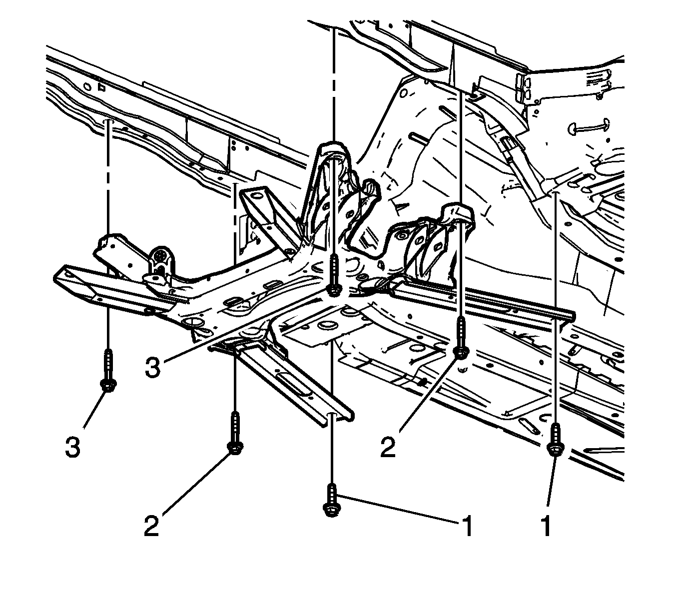
- Remove the frame rear (1) and center (2) mounting bolts.
- Loosen the front frame bolts (3) 12.7 mm (0.5 in) to 25.4 mm (1 in).
- Lower the rear section of the frame.
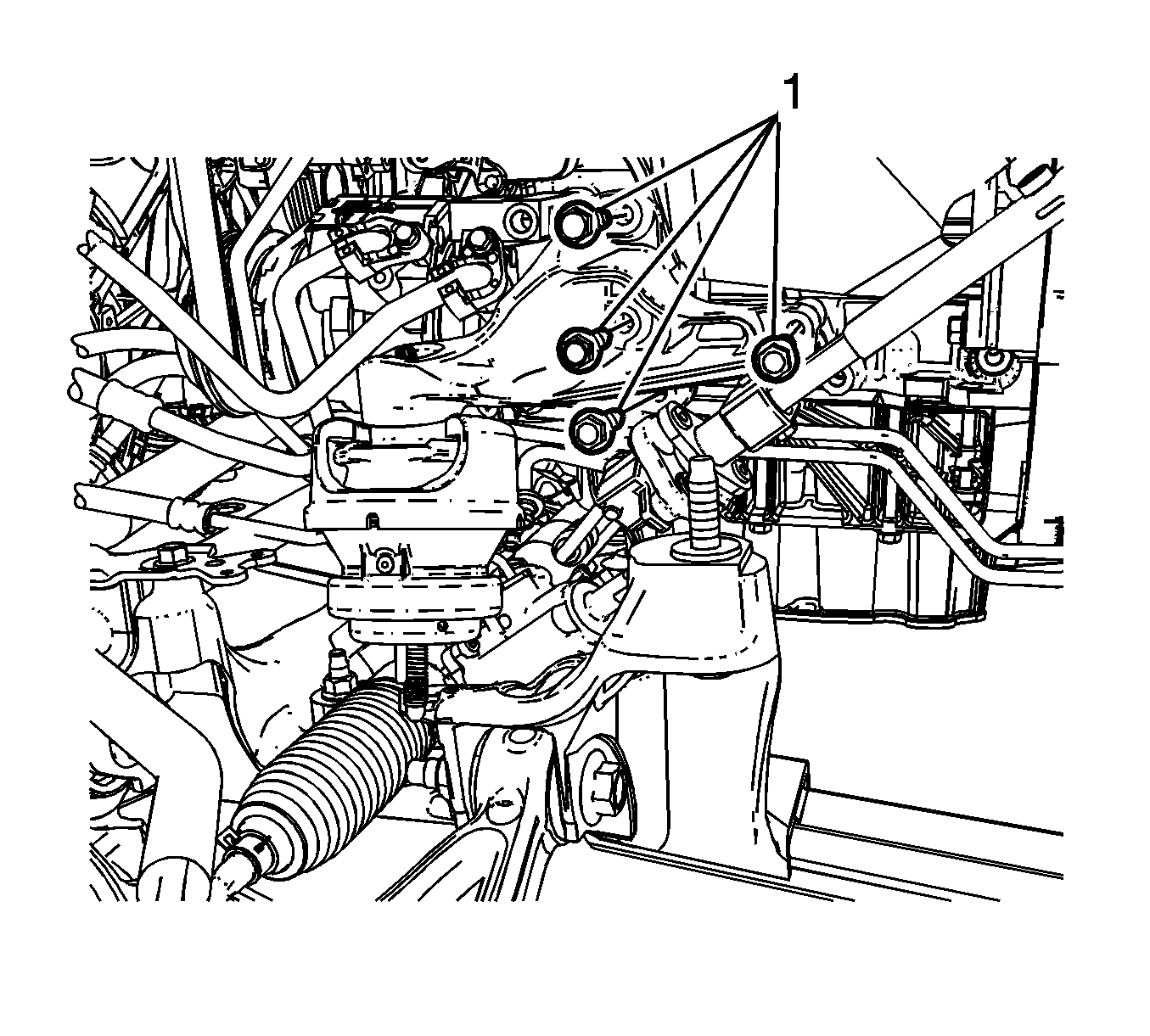
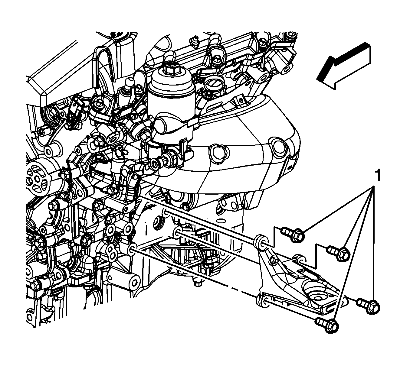
- Remove the engine mount bracket bolts (1).
- Remove the engine mount and engine mount bracket as an assembly.
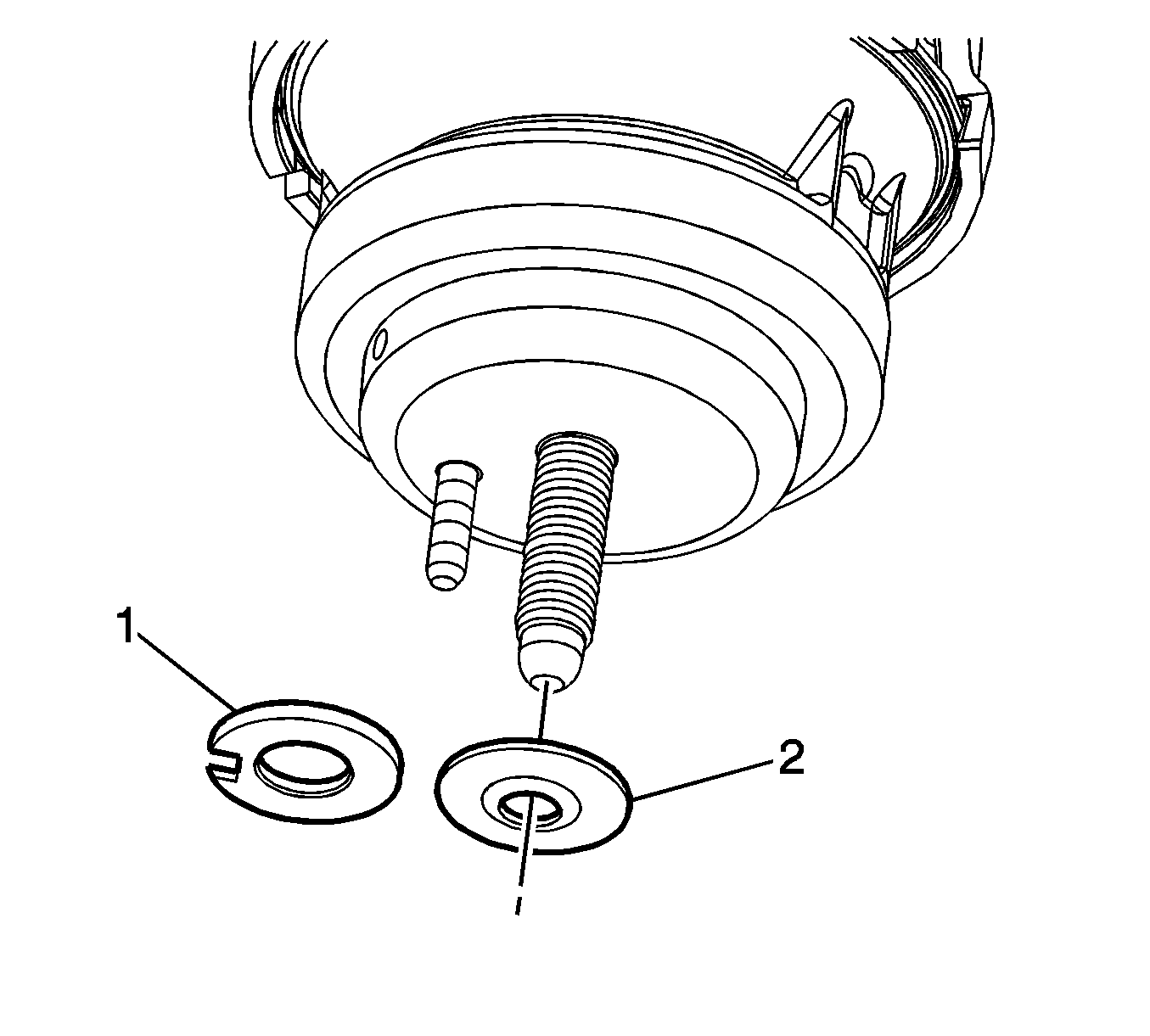
- Remove the washer (1) or (2) located between the engine mount and the frame.
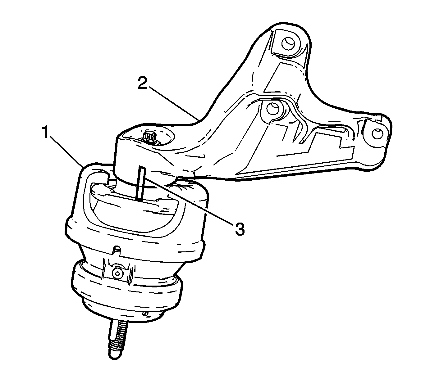
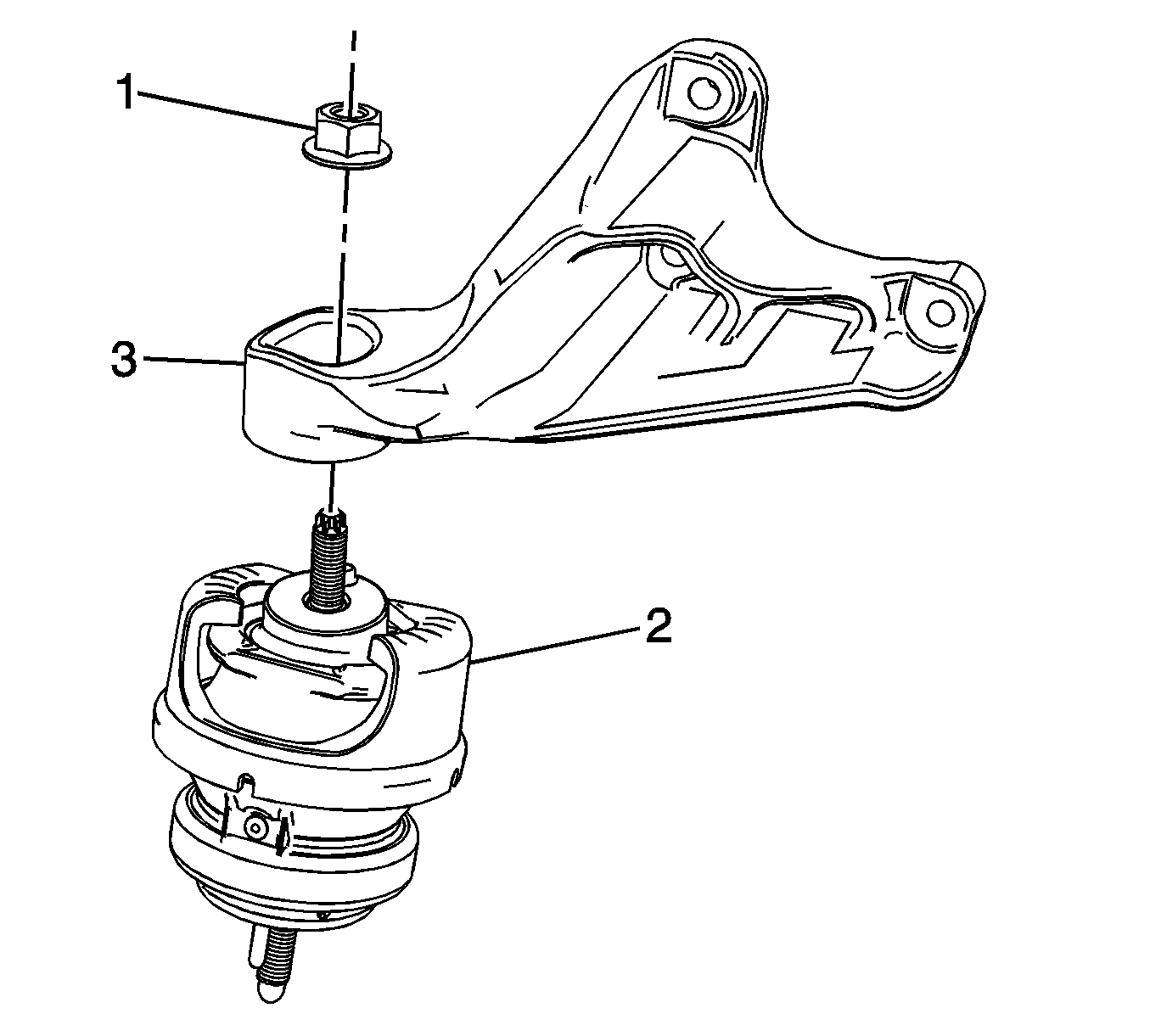
- Mark the location of the engine mount (1) to the engine mount bracket (2).
- Remove the upper engine mount retaining nut (1).
- Separate the engine mount (2) from the engine mount bracket (3).
Installation Procedure
- Position the engine mount bracket (3) to the engine mount (2).
- Align the location mark (3) of the engine mount (1) to the engine mount bracket (2).
- Install the upper engine mount retaining nut.
- Install the engine mount and engine mount bracket as an assembly.
- Install the engine mount bracket bolts (1).
- Ensure the slotted washer (1) or the plastisol insert washer (2) is properly installed between the engine mount and the frame.
- Raise the rear section of the frame.
- Install but do not tighten the frame rear (1) and center (2) mounting bolts.
- Tighten the frame bolts.
- Remove the screw jack from the rear of the front frame.
- Remove the screw jack and block of wood from under the oil pan.
- Install the left and right lower engine mount nuts.
- Install the lower section of the steering intermediate shaft. Refer to Lower Intermediate Steering Shaft Replacement.
- Unsecure the steering wheel.
- Install the tower brace. Refer to Cross Vehicle Brace Replacement.


Notice: Refer to Fastener Notice in the Preface section.
Tighten
Tighten the nut to 80 N·m (59 lb ft).

Tighten
Tighten the bolts to 60 N·m (44 lb ft).


Tighten
Tighten the bolts to 191 N·m (141 lb ft).
Important: Ensure to tighten the frame bolts in sequence.
| 9.1. | Tighten the left front frame bolt. |
Tighten
Tighten the bolt to 191 N·m (141 lb ft).
| 9.2. | Tighten the right front frame bolt. |
Tighten
Tighten the bolt to 191 N·m (141 lb ft).
| 9.3. | Tighten the center front frame bolts. |
Tighten
Tighten the bolts to 191 N·m (141 lb ft).
| 9.4. | Tighten the rear front frame bolts. |
Tighten
Tighten the bolts to 191 N·m (141 lb ft).
Tighten
Tighten the nuts to 80 N·m (59 lb ft).
Engine Mount Bracket Replacement - Left Side AWD
Removal Procedure
- Remove the engine mount. Refer to Engine Mount Replacement - Left Side.
- Remove the left engine mount bracket retaining bolts.
- Remove the left engine mount bracket.
Installation Procedure
- Install the left engine mount bracket assembly.
- Install the left engine mount bracket retaining bolts.
- Install the engine mount. Refer to Engine Mount Replacement - Left Side.

Notice: Refer to Fastener Notice in the Preface section.
Tighten
Tighten the bolts to 60 N·m (44 lb ft).
