For 1990-2009 cars only
Caution: Refer to Brake Fluid Irritant Caution in the Preface section.
Notice: Refer to Brake Fluid Effects on Paint and Electrical Components Notice in the Preface section.
Removal Procedure
- Disconnect the master cylinder fluid level sensor electrical connector.
- Remove the air inlet panel support bracket push nut from the master cylinder mounting stud.
- Carefully pull the air inlet panel support bracket outward and rotate the panel aside.
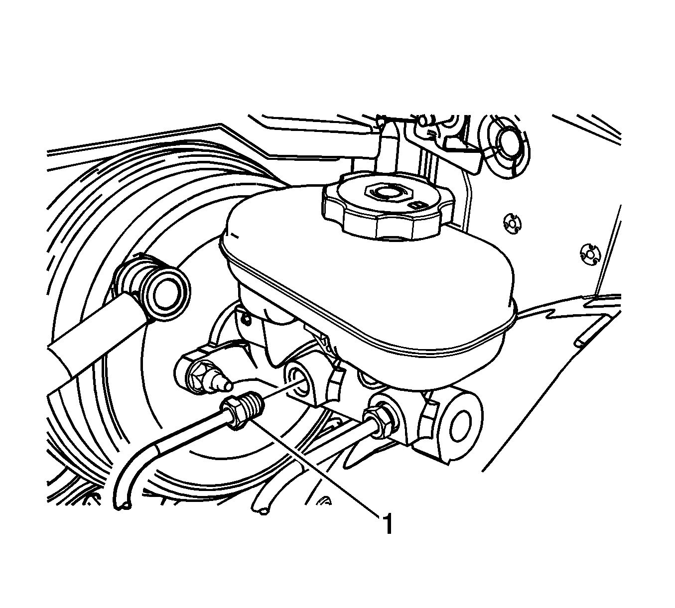
- Disconnect the master cylinder primary brake pipe fitting (1).
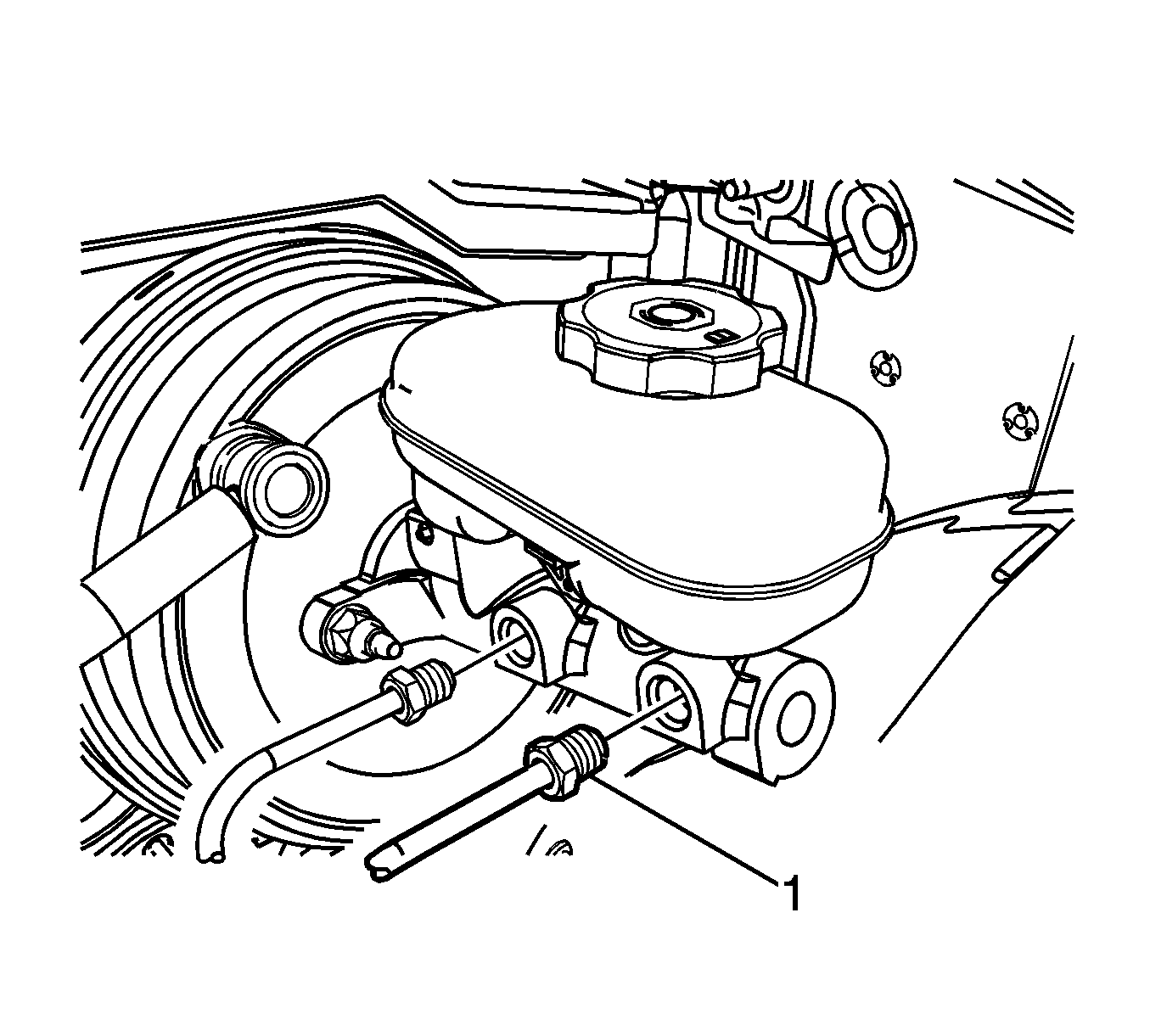
- Disconnect the master cylinder secondary brake pipe fitting (1).
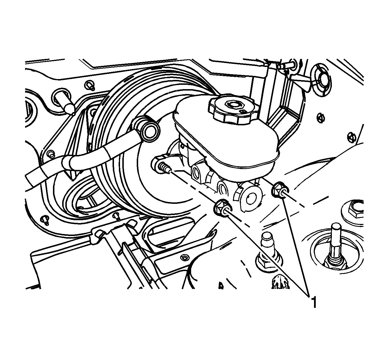
- Remove the 2 master cylinder nuts (1).
- Remove the master cylinder.

Cap the brake pipe fitting and plug the master cylinder outlet port to prevent brake fluid loss and contamination.

Cap the brake pipe fitting and plug the master cylinder outlet port to prevent brake fluid loss and contamination.

Installation Procedure
- If installing a new master cylinder, bench bleed the master cylinder. Refer to Master Cylinder Bench Bleeding.
- Install the master cylinder to the vacuum brake booster.
- Install the master cylinder nuts (1).
- Install the master cylinder secondary brake pipe fitting (1).
- Install the master cylinder primary brake pipe fitting (1).
- Connect the master cylinder fluid level sensor electrical connector.
- Rotate the air inlet panel and position the support bracket to the master cylinder mounting stud.
- Install the air inlet panel support bracket push nut.
- Bleed the hydraulic brake system. Refer to Hydraulic Brake System Bleeding.

Notice: Refer to Fastener Notice in the Preface section.
Tighten
Tighten the nuts to 25 N·m (18 lb ft).

Tighten
Tighten the fitting to 32 N·m (24 lb ft).

Tighten
Tighten the fitting to 32 N·m (24 lb ft).
