Outside Door Handle, Door Glass and/or Outside Mirror Inoperative (Replace Door Handle Switch, Inspect Doc-N-Loc Connector and/or Lubricate Door Handle)

| Subject: | Outside Door Handle, Door Glass and/or Outside Mirror Inoperative (Replace Door Handle Switch, Inspect Doc-N-Loc Connector and/or Lubricate Door Handle) |
| Models: | 2008 Cadillac CTS |
Condition
Important: The customer may use the key to enter the vehicle and the inside handle will still function normally to exit from inside the vehicle.
Some customers may comment on any of the following concerns:
| • | The door will not unlock or open from the outside door handle but the door will open with the key. |
| • | The door glass is inoperative -- will not roll up or down (left or right). |
| • | The outside mirror is inoperative (left or right). |
| • | The door handle sticks in the open position (left or right). |
Cause
These conditions may be caused by one of the following:
| • | An inoperative outside door handle switch. |
| • | A short to ground or an open in the door or door trim wire harness. |
| • | An intermittent or poorly seated door trim harness to door harness doc-n-loc X505 or X605 connector. |
| • | The outside door handle may be lacking lubricant. |
Correction 1
Check for codes.
Inoperative Left Door Outside Handle Switch (If the door handle sticks in the open position for longer than one minute, the door will not open and diagnostic code B3849 will be set if the failure was less than 50 ignition cycles prior to checking codes)
- Remove the window switch, Refer to Door Lock and Window Switch Replacement Driver Side (DDM) in SI.
- Disconnect the door lock/window switch-driver (DDM) X6 connector.
- With a DVOM connected to ground and pin 2 circuit 5881 in the door lock/window switch-driver (DDM) X6 connector, the readings should be less than 20 ohms with the handle in the open position.
- With a DVOM connected to ground and pin 4 circuit 5882 in the door lock/window switch-driver (DDM) X6 connector, the readings should be less than 20 ohms with the handle in the open position.
- If resistance is higher, remove the door trim. Refer to Front Side Door Trim Panel in SI.
- Check the resistance at the doc-n-loc X505 female connector, pin 11 circuit 5881 and pin 2 circuit 350. Reading should be less than 20 ohms with the door handle in the open position.
- With the handle in the open position the resistance should be less than 20 ohms on pin 12 circuit 5882 and pin 2 circuit 350. If the values are correct at the X505 connector continue with Step 8. If the values are incorrect, proceed to Step 14.
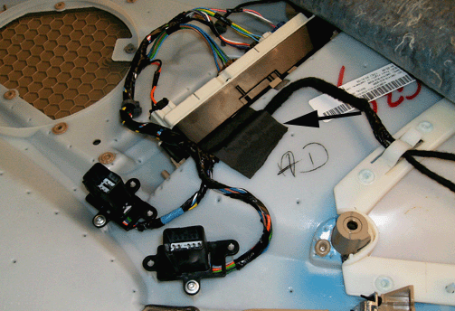
- Relocate the wiring harness by moving it away for the doc-n-loc on the trim panel and apply duct tape to the harness.
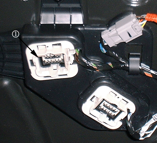
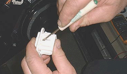
- The doc-n-loc is out of position, remove the upper doc-n-loc connector from the bracket. The white connector housing has six tabs that have to be released.
- Slide the white housing off the connector and adjust the locking tab on the connector and reinstall.
- Remove the doc-n-loc bracket from the door and connect the bracket to the door trim. A click noise will be heard.
- Install the door trim.
- When installing the trim screws, start with the one closest to the doc-n-loc and check the operation.
- Unplug the door switch connector.
- Check the wiring harness from the door switch connector pin C and pin F to the doc-n-loc connector pin 2 (female).
- Check the wiring harness from the door switch connector pin D to the doc-n-loc connector pin 11. Check the wiring harness from the door switch connector pin E to the doc-n-loc connector pin 12. Resistance should be less than 20 ohms. If not, check for an open in the harness and make the repair as necessary. If the values are correct, continue with Step 17.
- Replace the door handle housing assembly. (The switch is part of the assembly.)
- Remove the outside handle lock cylinder cap bolt plug (located on the inside upper door frame).
- Remove the bolt that retains the lock cylinder cap.
- With the door handle in the open position, remove the door lock cap.
- Disconnect the electrical connector from the front of the handle.
- With the door handle in the open position, hold the counterbalance down and pull back on the outside handle to disengage it from the handle housing.
- Remove the door handle housing bolt.
- Disconnect the electrical connector from the door handle switch.
- Disconnect the lock rod.
- Remove the housing through the opening in the inner panel and transfer the lock cylinder and handle release rod to the new housing.
- Install the door handle housing kit.
- Install the door handle housing bolt.
- Install the lock rod.
- Install the electrical connector for the door handle switch.
- Place the counterbalance in the open position and install the handle.
- With the door handle in the open position, install the door lock cap.
- Install the bolt that retains the lock cylinder cap.
- Remove the doc-n-loc bracket from the door and connect the doc-n-loc together on the door trim. A click noise will be heard.
- Install the door trim.
- When installing the trim screws, start with the number one closest to the doc-n-loc.
- Clear codes.
Notice: Damage may occur to the handle switch if counterbalance is not held in the open position when removing the handle.
Tighten
Tighten the bolt to 7 N·m (62 lb in).
Tighten
Tighten the bolt to 9N·m (80 lb in).
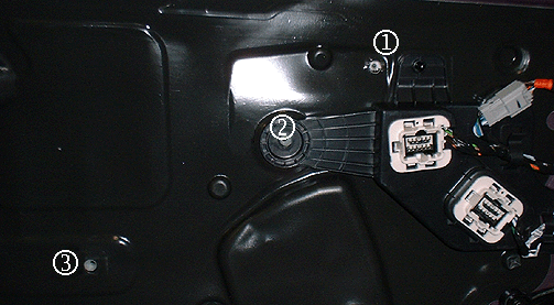
Tighten
Tighten the screws to 7 N·m (62 lb in).
Correction 2
Check for codes.
Inoperative Right Door Outside Door Handle Switch (if the door handle sticks in the open position for longer than one minute, the door will not open)
- Remove the window switch. Refer to Door Lock and Window Switch Replacement-Driver Side (PDM) in SI.
- Disconnect the door lock/window switch-driver (PDM) X6 connector.
- With a DVOM connected to ground and pin 2 circuit 5878 in the door lock/window switch-driver (DDM) X6 connector, the readings should be less than 20 ohms with the handle in the open position.
- With a DVOM connected to ground and pin 4 circuit 5879 in the door lock/window switch-driver (DDM) X6 connector, the readings should be less than 20 ohms with the handle in the open position.
- If resistance is higher, remove the door trim. Refer to Front Side Door Trim Panel in SI.
- Check the resistance at the doc-n-loc X605 female connector, pin 2 circuit 450 and pin 11 circuit 5878. The reading should be less than 20 ohms with the handle in the open position.
- With the handle in the open position, the resistance should be less than 20 ohms on pin 2 circuit 450 and pin 12 circuit 5879. If the values are correct, at the X605 continue with Step 8. If the values are incorrect, proceed to Step 14.
- Relocate the wiring harness by moving it away for the doc-n-loc on the trim panel and apply duct tape to the harness.
- The doc-n-loc is out of position, remove the upper doc-n-loc connector from the bracket. The white connector housing has six tabs that have to be released.
- Slide the white housing off the connector and adjust the locking tab on the connector and reinstall.
- Remove the doc-n-loc bracket from the door and connect to the door trim. A click noise will be heard.
- Install the door trim.
- When installing the trim screws, start with number one the closest to the doc-n-loc and check the operation.
- Unplug the door switch connector.
- Check the wiring harness from the door switch connector pin C and pin F to the doc-n-loc connector pin 2 (female).
- Check the wiring harness from the door switch connector pin D to the doc-n-loc connector pin 11. Check the wiring harness from the door switch connector pin E to the doc-n-loc connector pin 12. Resistance should be less than 20 ohms. If not, check for an open in the harness and make the repair as necessary. If the values are correct, continue with Step 17.
- Replace the door handle housing assembly. (The switch is part of the assembly.)
- Remove the outside handle lock cylinder cap bolt plug (located on the inside upper door frame).
- Remove the bolt that retains the lock cylinder cap.
- With the door handle in the open position, remove the door lock cap.
- Disconnect the electrical connector from the front of the handle.
- With the door handle in the open position, hold the counterbalance down and pull back on the outside handle to disengage it from the handle housing.
- Remove the door handle housing bolt.
- Disconnect the electrical connector from the door handle switch.
- Disconnect the lock rod.
- Remove the housing through the opening in the inner panel and transfer the lock cylinder and handle release rod to the new housing.
- Install the door handle housing kit.
- Install the door handle housing bolt.
- Install the lock rod.
- Install the electrical connector for the door handle switch.
- Place the counterbalance in the open position and install the handle.
- With the door handle in the open position, install the door lock cap.
- Install the bolt that retains the lock cylinder cap.
- Remove the doc-n-loc bracket from the door and connect the doc-n-loc together on the door trim. A click noise will be heard.
- Install the door trim.
- When installing the trim screws, start with number one the closest to the doc-n-loc connector.
- Clear codes.


Notice: Damage may occur to the handle switch if the counterbalance is not held in the open position when removing the handle.
Tighten
Tighten the bolt to 7 N·m (62 lb in).

Tighten
Tighten the screws to 2N·m (18 lb in).
Correction 3
Check for codes
Left or Right Door Handle Stuck in the Open Position When Door is Closed (apply lubricant to the door handle pivot area - vehicles built prior to 5/18/2008)
- Remove the door trim. Refer to Front Side Door Trim Panel in SI.
- Remove the outside handle lock cylinder cap bolt plug (located on the inside upper door frame).
- Remove the bolt that retains the lock cylinder cap.
- With the door handle in the open position, remove the door lock cap.
- Disconnect the electrical connector from the front of the handle.
- With the door handle in the open position, hold the counterbalance down and pull back on the outside handle to disengage it from the handle housing.
- Apply Lubriplate Lubricant to both sides of the front pivot area of the handle and on the rear part of the handle.
- Place the counterbalance in the open position and install the handle.
- Connect the electrical connector to the handle.
- With the door handle in the open position, install the door lock cap.
- Install the bolt that retains the lock cylinder cap.
- Install the door trim.
- When installing the trim screws, start with number one closest to the doc-n-loc connector.
- Clear codes.
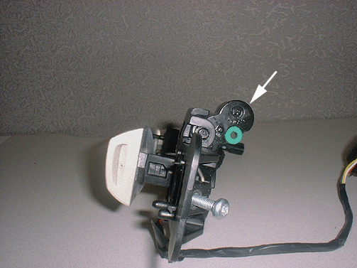
Notice: Damage may occur to the handle switch if the counterbalance is not held in the open position when removing the handle.
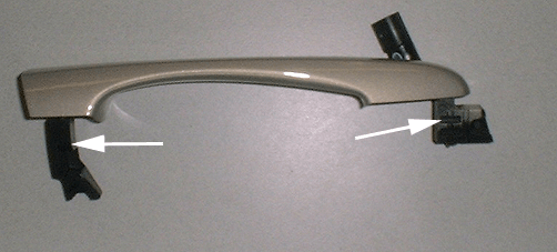
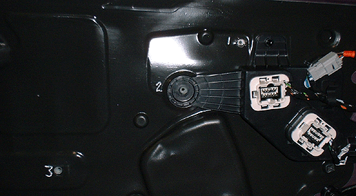
Tighten
Tighten the screws to 2 N·m (18 lb in).
Correction 4
If the Outside Mirrors and/or Power Windows are Inoperative (inspect the dock and lock connector)
- Remove the door trim. Refer to Front Side Door Trim Panel in SI.
- Remove the dock and lock assembly from the door and connect the assembly to the door trim. A click noise will be heard.
- Reinstall the door trim. Refer to Front Side Door Trim Panel in SI.
- When installing the trim screws, start with the one closest to the doc-n-loc.
- Check the operation of the outside mirrors and power windows. If the concern is still present, refer to diagnostic information in SI.
- If the condition is still present after performing all of the above steps check for intermittent power and ground or GMLAN Serial DATA at the door zone module refer to SI if necessary.
Parts Information
Part Number | Description |
|---|---|
25864471 | Housing Kit, Frt S/D O/S HDL (Uplevel) W/2 Connector - Left |
25864472 | Housing Kit, Frt S/D O/S HDL (Uplevel) W/2 Connector - Right |
25864473 | Housing Kit, FRT S/D O/S HDL Left (Base) W/1 Connector |
25864474 | Housing Kit, FRT S/D O/S HDL Right (Base) W/1 Connector |
89021668 (U.S.) 89021674 (Canada) | Lubriplate Lubricant |
Warranty Information
For vehicles repaired under warranty, use:
Labor Operation | Description | Labor Time |
|---|---|---|
B4127 | Front Side Door Outside Handle Housing | Use Published Labor Operation Time |
B4120 | Front Side Door Outside Handle Replacement - Right Side | |
B4121 | Front Side Door Outside Handle Replacement - Left Side | |
N6636 | Wiring and/or Connector - Entry Control System - Repair or Replace |
