For 1990-2009 cars only
Removal Procedure
- Raise and support the vehicle. Refer to Lifting and Jacking the Vehicle.
- Remove the front tire and wheel assembly. Refer to Tire and Wheel Removal and Installation.
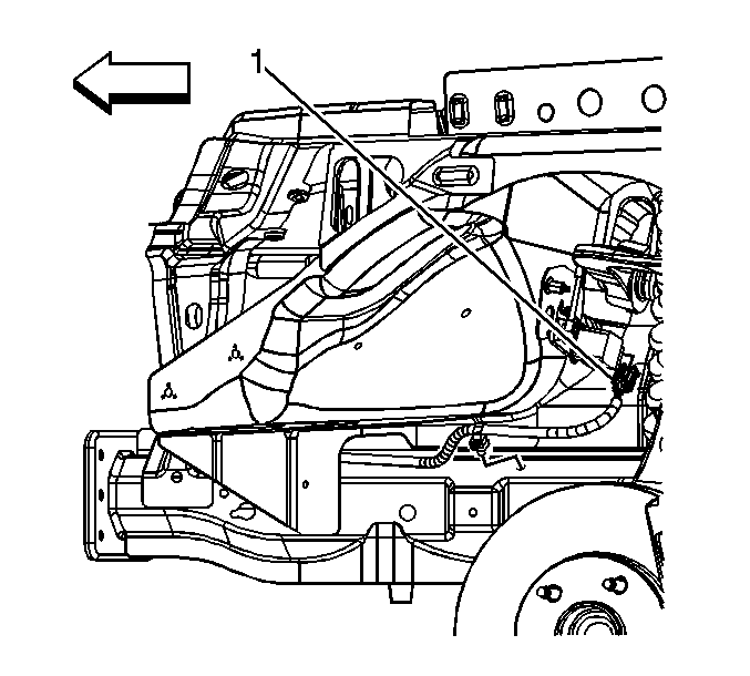
- Disconnect the electrical connector (1).
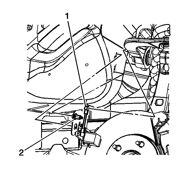
- Disconnect the ball and socket (1) from upper control arm.
- Loosen the clinch nut (2) from the stud.
- Rotate and remove the sensor from the wheelhouse panel.


Installation Procedure
- Position and rotate the sensor (1) and the locking tab into the holes in the wheelhouse panel.
- Secure the clinch nut (2) on the stud to the wheelhouse panel and tighten to 9 N·m (80 lb in).
- Lock the ball socket (1) to upper control arm ball stud.
- Connect the electrical connector (1) to the sensor assembly.
- Install the tire and wheel assembly. Refer to Tire and Wheel Removal and Installation.
- Lower the vehicle.
- Set up and program the headlamp control module. Refer to Control Module References.

Caution: Refer to Fastener Caution in the Preface section.


