Lower Control Arm Replacement AWD
Special Tools
J 43631 Ball Joint Separator
Removal Procedure
- Raise and support the vehicle. Refer to Lifting and Jacking the Vehicle.
- Remove the tire and wheel. Refer to Tire and Wheel Removal and Installation.
- Remove the air deflector. Refer to Front Air Deflector Replacement.
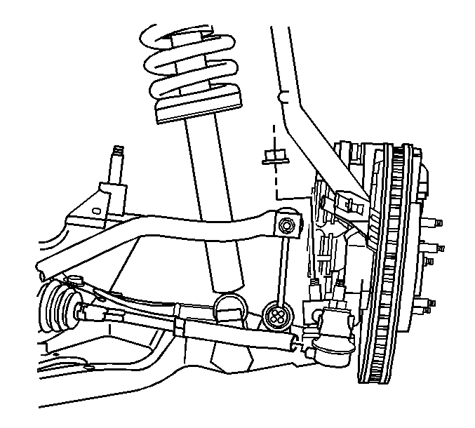
- Remove the stabilizer shaft link from the lower control arm. Refer to Stabilizer Shaft Link Replacement.
- Remove the wheel speed sensor. Refer to Front Wheel Speed Sensor Replacement.
- Remove the lower ball joint nut (2).
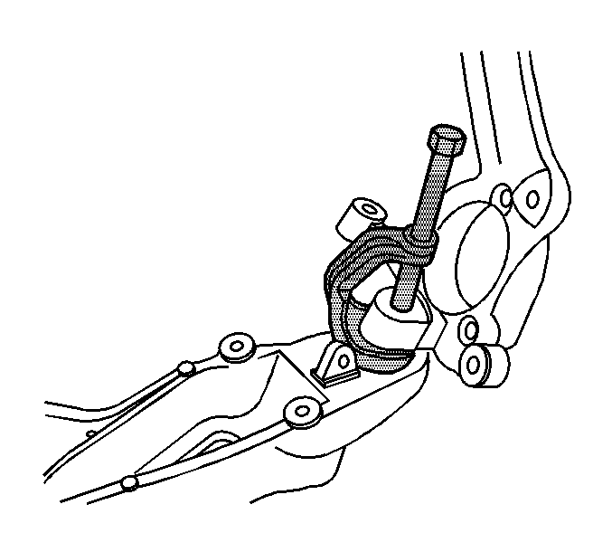
- Using the J 43631 , remove the ball joint stud from the steering knuckle.
- Remove the yoke from the stud on the lower control arm. Refer to Front Shock Absorber Yoke Replacement
- Loosen the power steering gear retaining bolts and raise the power steering gear. Refer to Steering Gear Replacement.
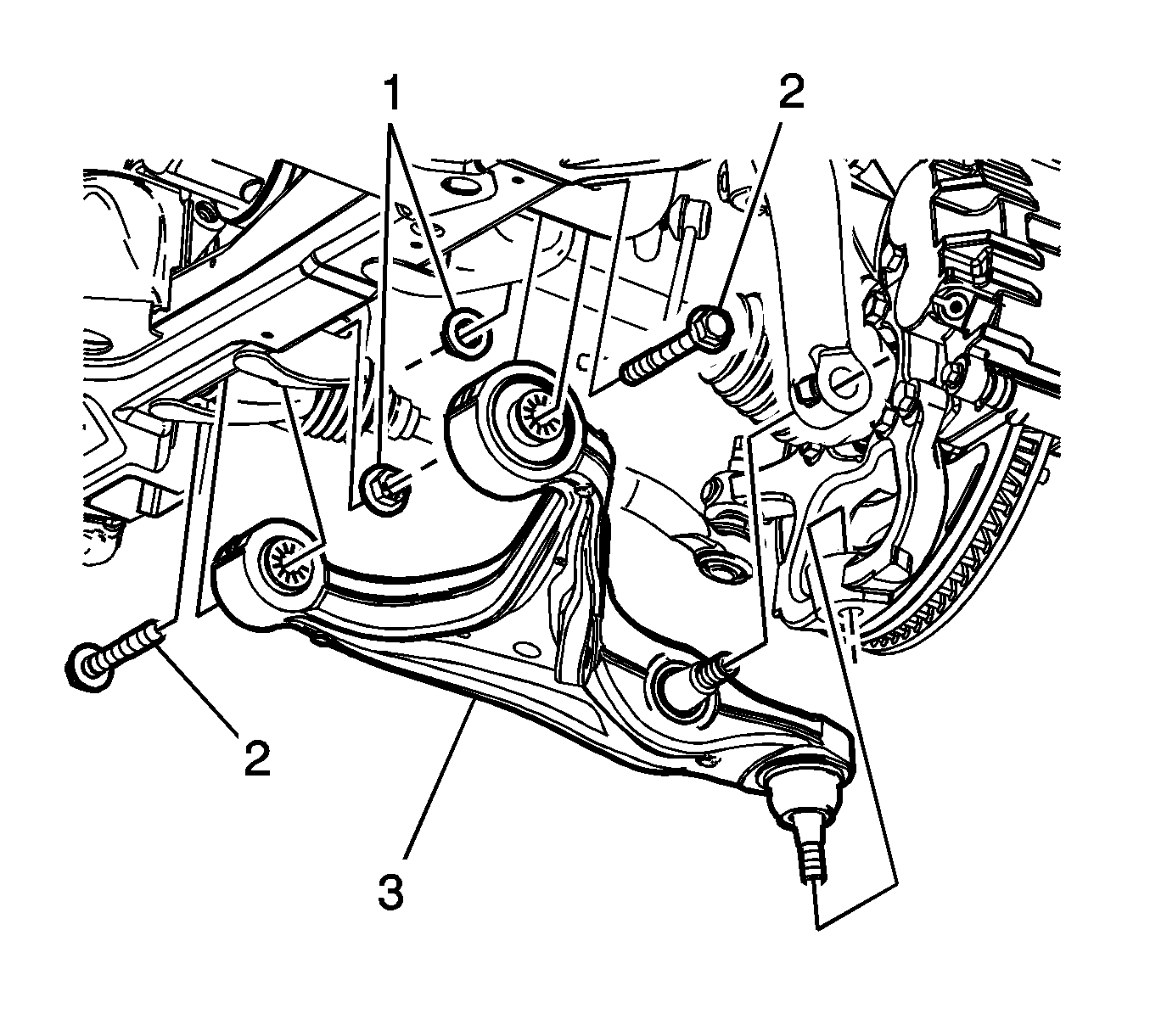
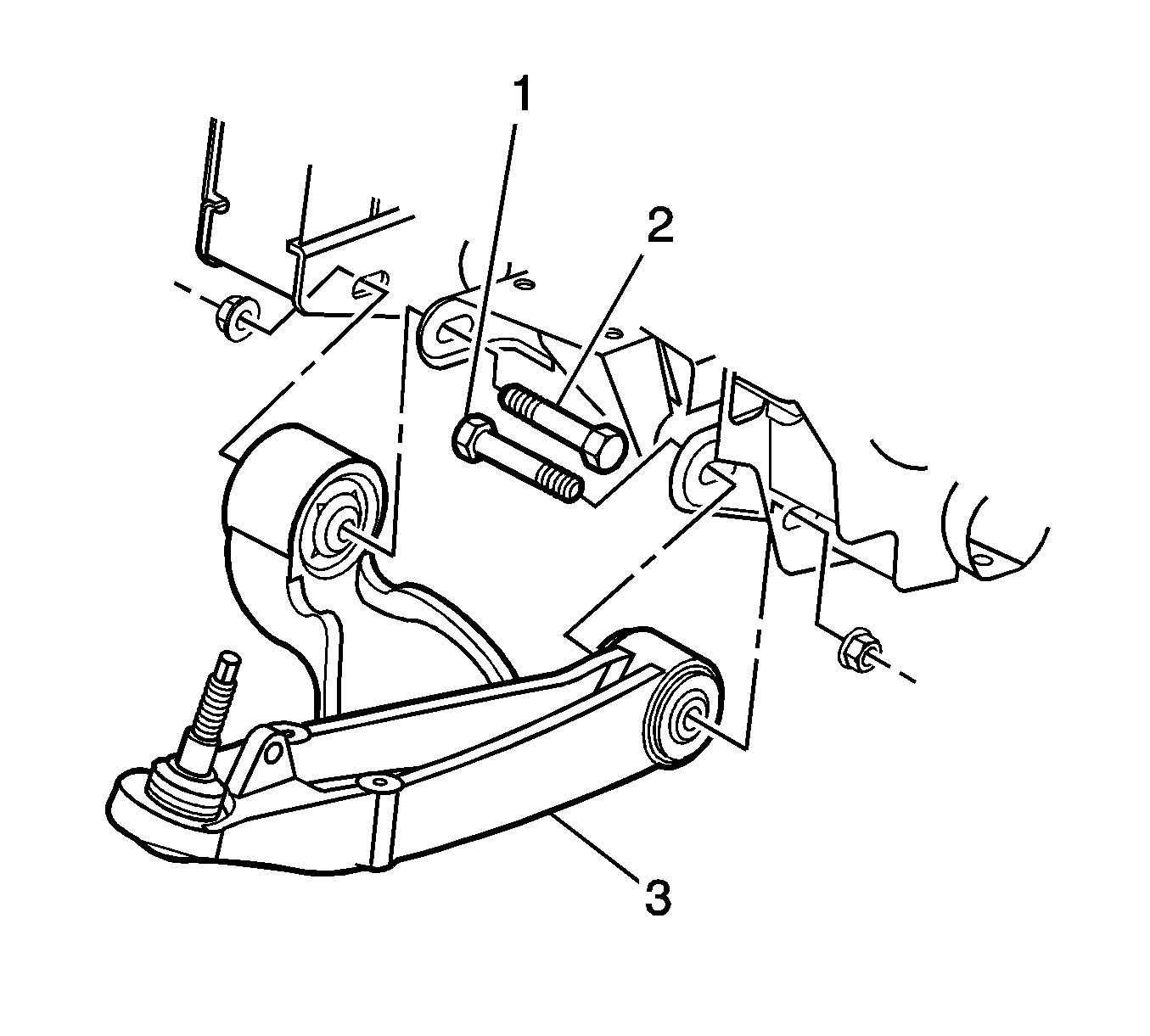
- Remove the lower control arm to cradle nuts (1).
- Remove the lower control arm to cradle bolts (2).
- Remove the lower control arm (3) from the vehicle.
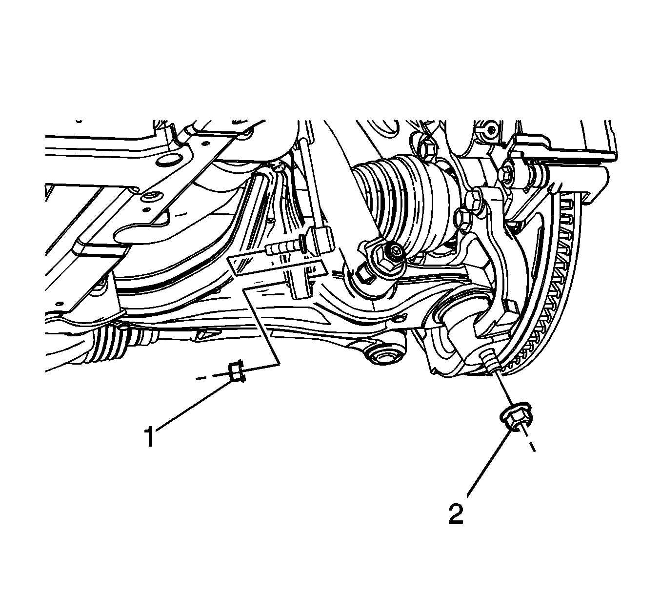
Caution: The ball stud must not rotate during disassembly or reassembly. Hand tools must be used to keep the ball stud from rotating. If air tools are used and the stud is allowed to rotate, damage to the ball stud and/or stud mounting hole may occur.
Note: Raise the power steering gear to provide clearance when removing the rear lower control arm to frame retaining bolt.
Installation Procedure
- Position the lower control arm (3) to the vehicle.
- Install the lower control arm to cradle bolts (2).
- Install the lower control arm to cradle nuts (1) and tighten to 135 N·m (96 lb ft).
- Tighten the power steering gear retaining bolts. Refer to Steering Gear Replacement.
- Install the shock module yoke to the lower control arm nut. Refer to Front Shock Absorber Yoke Replacement.
- Install the lower control arm ball joint nut (1).
- Install the wheel speed sensor. Refer to Front Wheel Speed Sensor Replacement.
- Install the stabilizer shaft link to the lower control arm. Refer to Stabilizer Shaft Link Replacement.
- Install the air deflector. Refer to Front Air Deflector Replacement.
- Install the tire and wheel. Refer to Tire and Wheel Removal and Installation.
- Lower the vehicle.
- Check the front end alignment. Refer to Wheel Alignment Measurement.

Caution: Refer to Fastener Caution in the Preface section.
Note: Tighten the lower control arm bolts and nuts with the lower control arm at normal vehicle ride height.

Caution: The ball stud must not rotate during disassembly or reassembly. Hand tools must be used to keep the ball stud from rotating. If air tools are used and the stud is allowed to rotate, damage to the ball stud and/or stud mounting hole may occur.
| 6.1. | Tighten the nut to 40 N·m (130 lb ft). |
| 6.2. | Rotate the nut an additional 120 degrees. |
Lower Control Arm Replacement RWD
Special Tools
J 43631 Ball Joint Remover
Removal Procedure
- Raise and support the vehicle. Refer to Lifting and Jacking the Vehicle.
- Remove the tire and wheel. Refer to Tire and Wheel Removal and Installation.
- Remove the stabilizer shaft link from the lower control arm. Refer to Stabilizer Shaft Link Replacement
- Remove the shock assembly lower retaining bolts. Refer to Shock Absorber and Spring Assembly Replacement.
- Remove the shock absorber yoke from the lower control arm. Refer to Front Shock Absorber Yoke Replacement.
- Remove the outer tie rod to the steering knuckle retaining nut. Refer to Steering Linkage Outer Tie Rod Replacement.
- Remove the ABS wire harness from the lower control arm.
- Remove the front and rear lower control arm mounting nuts.
- Remove the front and rear lower control arm mounting bolts.
- Lower and support the lower arm control to gain access to the lower ball joint.
- Remove the front lower control arm front nut and discard.
- Using the J 43631 remover , separate the lower ball joint from the steering knuckle.
- Remove the lower control arm from the vehicle.
Note: Step 5 is for rear wheel drive (RWD) vehicles only.
Note: Step 6 is for all wheel drive (AWD) vehicles only.
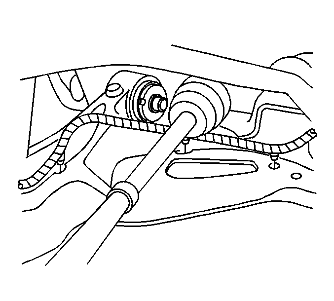
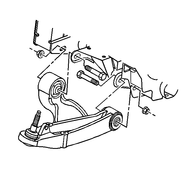
Installation Procedure
- Position the lower control arm (3) to the vehicle.
- Install the front lower control arm mounting bolt (1) to tighten to 200 N·m (148 lb ft).
- Install the rear lower control arm mounting bolt (2) to tighten to 320 N·m (236 lb ft).
- Install the ABS wire harness to the lower control arm.
- Connect the lower ball joint to the steering knuckle.
- Install a NEW front lower control arm front nut.
- Tighten the lower ball joint retaining nut in the following order:
- Connect the outer tie rod to the steering knuckle.
- Install the steering linkage outer tie rod nut. Refer to Steering Linkage Outer Tie Rod Replacement.
- Install the shock assembly lower retaining bolts. Refer to Shock Absorber and Spring Assembly Replacement.
- Install the shock absorber yoke from the lower control arm. Refer to Front Shock Absorber Yoke Replacement.
- Install the stabilizer shaft link to the lower control arm. Refer to Stabilizer Shaft Link Replacement
- Adjust the lower control arm to Z height. Refer to Trim Height Specifications.
- Install the tire and wheel. Refer to Tire and Wheel Removal and Installation.
- Lower the vehicle.
- Align the front end. Refer to Wheel Alignment Measurement.
Caution: Refer to Fastener Caution in the Preface section.


| 7.1. | Tighten the front lower control arm front nut to 40 N·m (30 lb ft). |
| 7.2. | Tighten the front lower control arm front nut to an additional 120 degree turn. |
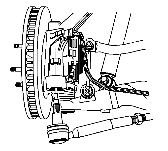
Note: Step 10 is for rear wheel drive (RWD) vehicles only.
Note: Step 11 is for all wheel drive (AWD) vehicles only.
