Engine Mount Replacement - Left Side RWD

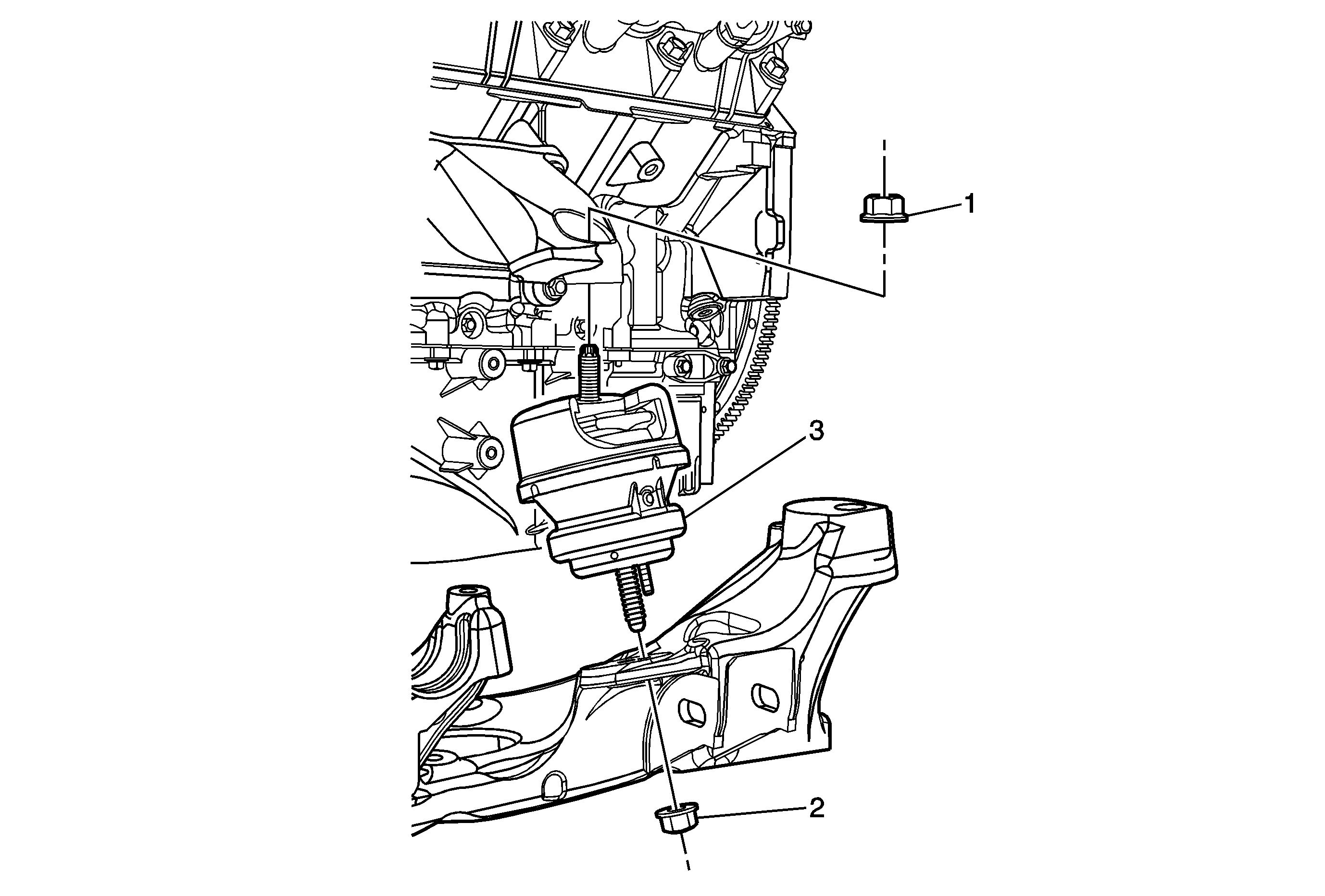
Callout | Component Name |
|---|---|
Preliminary Procedures
| |
1 | Engine Mount Fastener Caution: Refer to Component Fastener Tightening Caution in the Preface section. Procedure
Tighten |
2 | Engine Mount Fastener ProcedureThe engine mount nuts must be replaced once loosened or removed. Tighten |
3 | Engine Mount Procedure
|
Engine Mount Replacement - Left Side AWD
Removal Procedure
Caution: Secure the steering wheel utilizing a strap to prevent rotation. Locking of the steering column will prevent damage and a possible malfunction of the SIR system. The steering wheel must be secured
in position before disconnecting the following components:
• The steering column • The intermediate shaft • The steering gear
- Disconnect the battery ground cable. Refer to Battery Negative Cable Disconnection and Connection.
- Remove the cross vehicle brace. Refer to Cross Vehicle Brace Replacement.
- Remove the exhaust system. Refer to Exhaust System Replacement.
- Remove the right and left lower engine mount retaining nuts.
- Disconnect the lower intermediate steering shaft from the steering gear and position the shaft aside. Refer to Intermediate Steering Shaft Replacement.
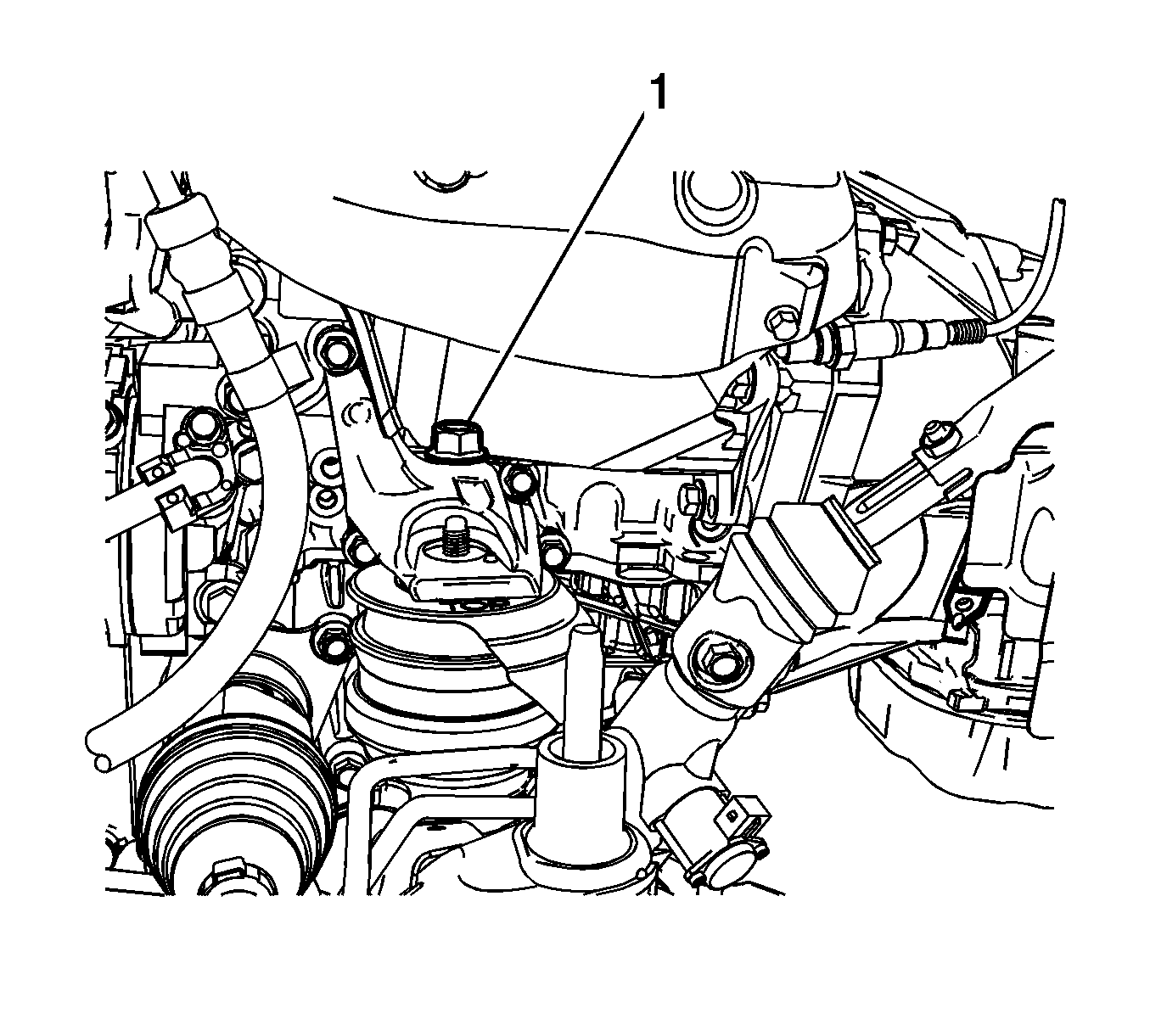
- Remove the upper engine mount retaining nut (1).
- Install a screw jack with a block of wood under the oil pan for support.
- Support the rear of the front frame with a screw jack.
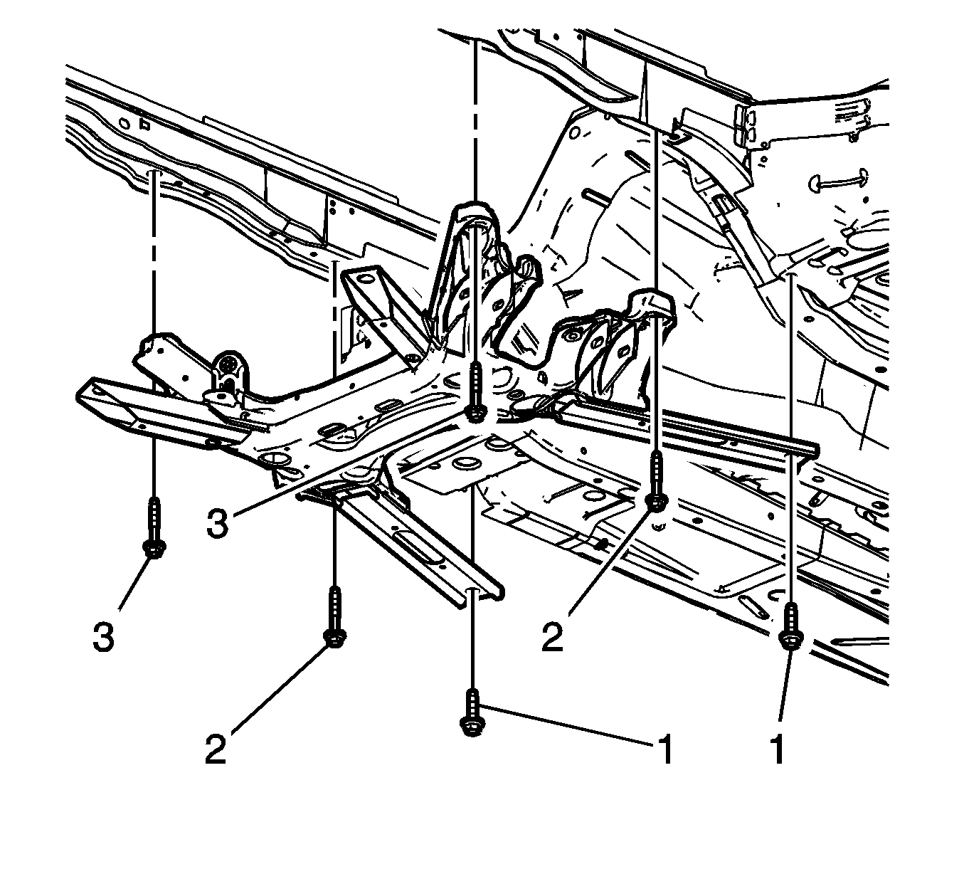
- Remove the frame rear (1) and center (2) mounting bolts.
- Loosen the front frame bolts (3) 12.7 mm (0.5 in) to 25.4 mm (1 in).
- Lower the rear section of the frame.
- Raise the engine using the screw jack until the weight is removed from the mount.
- Lower the screw jack under the frame.
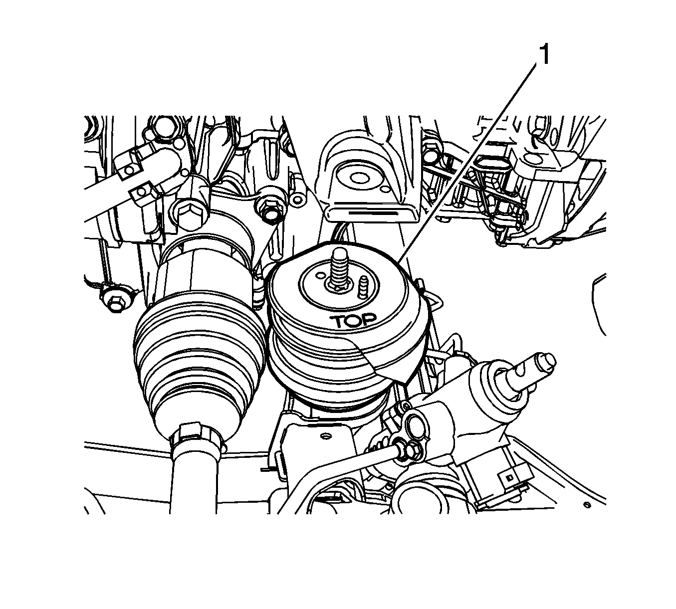
- Remove the engine mount (1) from the vehicle.


Installation Procedure
- Install the engine mount (1).
- Raise the rear section of the frame.
- Install but do not tighten the frame rear (1) and center (2) mounting bolts.
- Tighten the frame bolts.
- Remove the screw jack from the rear of the front frame.
- Remove the screw jack and block of wood from under the oil pan.
- Install the upper engine mount retaining nut (1) and tighten to 80 N·m (59 lb ft).
- Install the right and left lower engine mount retaining nuts and tighten to 80 N·m (59 lb ft).
- Connect the lower intermediate steering shaft to the steering gear. Refer to Intermediate Steering Shaft Replacement.
- Install the exhaust system. Refer to Exhaust System Replacement.
- Lower the vehicle.
- Install the cross vehicle brace. Refer to Cross Vehicle Brace Replacement.
- Connect the battery ground cable. Refer to Battery Negative Cable Disconnection and Connection.


Caution: Refer to Fastener Caution in the Preface section.
Note: Ensure to tighten the frame bolts in sequence.
| 4.1. | Tighten the left front frame bolt to 191 N·m (141 lb ft). |
| 4.2. | Tighten the right front frame bolt to 191 N·m (141 lb ft). |
| 4.3. | Tighten the center front frame bolts to 191 N·m (141 lb ft). |
| 4.4. | Tighten the rear front frame bolts to 191 N·m (141 lb ft). |

