For 1990-2009 cars only
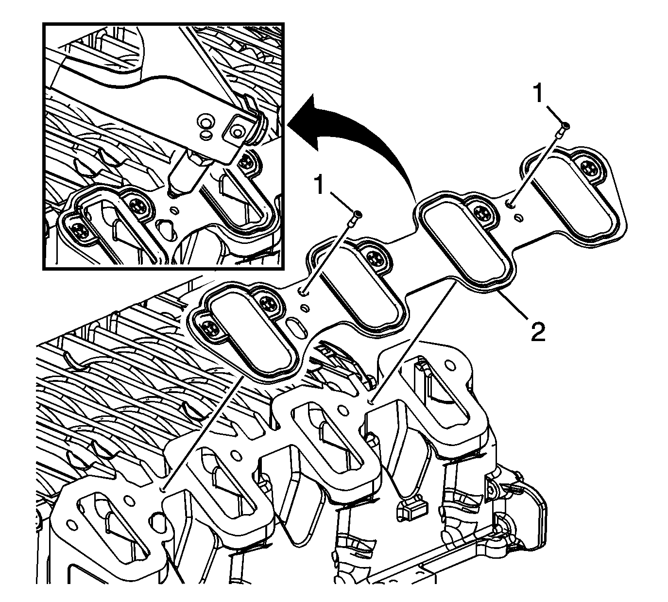
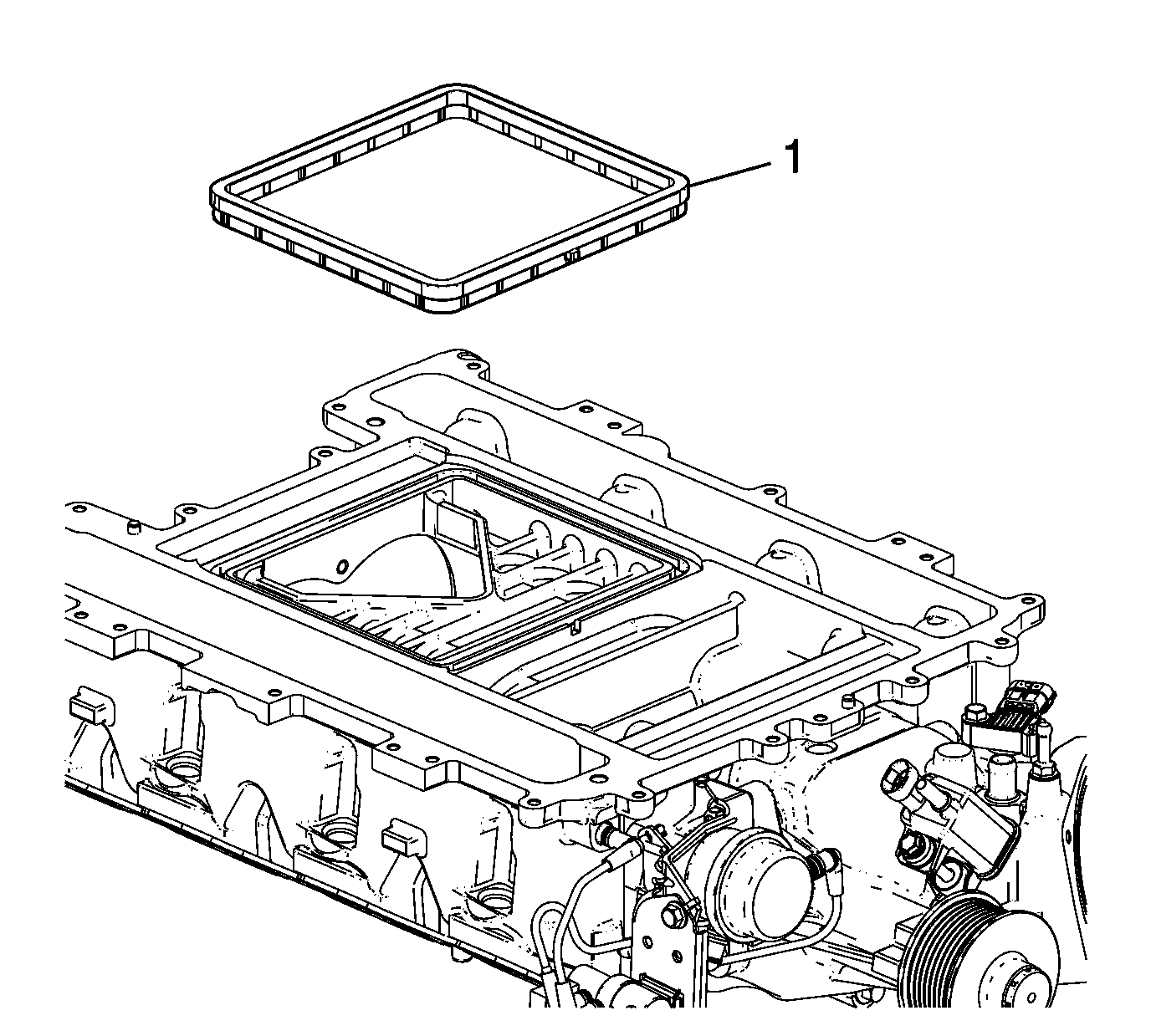
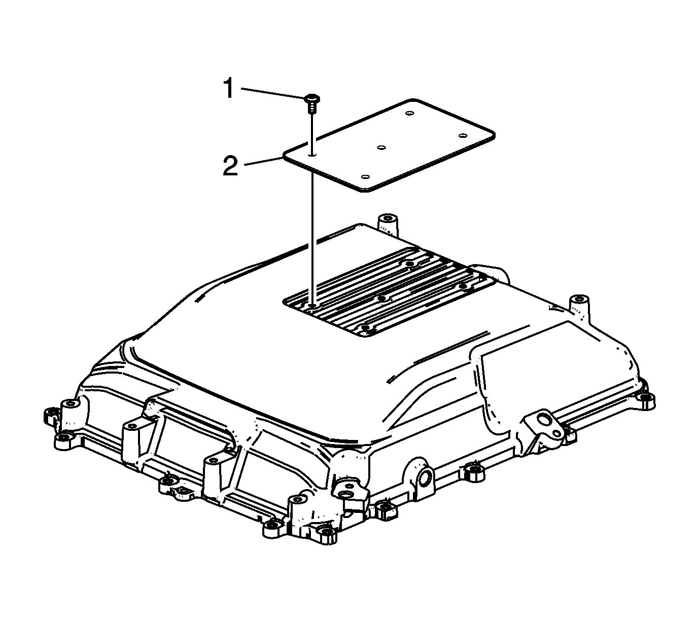
- Install the NEW gaskets (2).
- Install NEW gasket rivets (1).
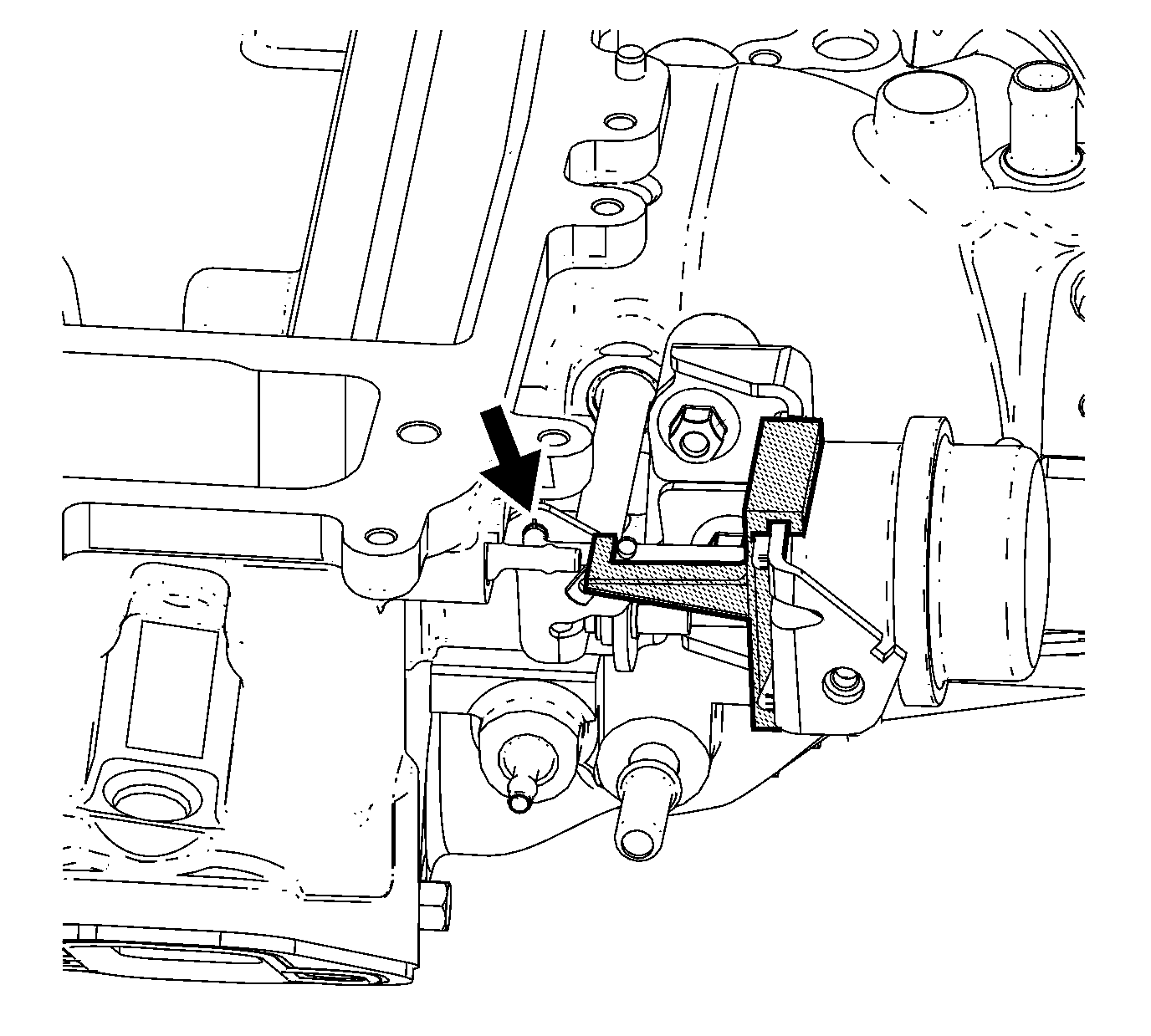
- Install the actuator adjustment tool onto the actuator. Position the raised portion of the rod in the proper position.
- Install the rod of the actuator into the lever of the supercharger.
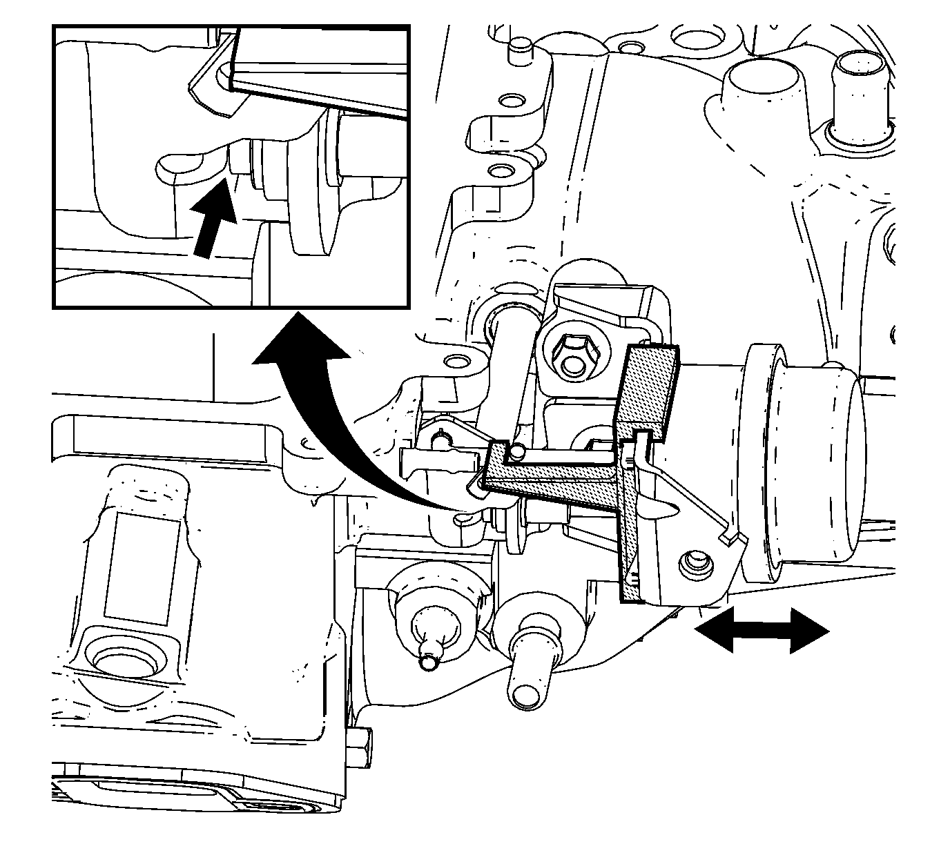
- Rotate the actuator and install the bolts. Do not tighten the bolts at this time.
- Moving the actuator forward or rearward as required, ensure that the supercharger lever is in contact with the adjustment screw on the actuator and that the lever is rotated to the fully closed position.
- Tighten the actuator bolts to 25 N·m (18 lb ft).
- Remove the adjustment tool from the actuator.
- Rotate the adjustment screw on the actuator clockwise ¼ turn.
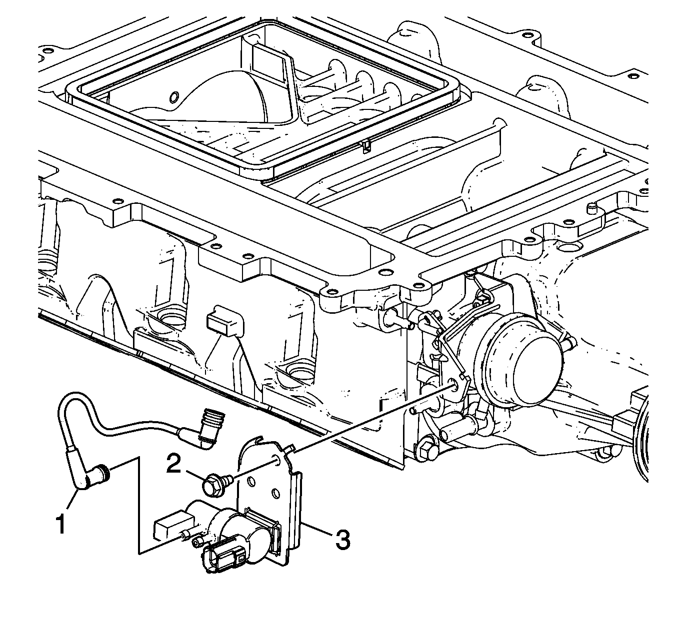
- Install the charge air bypass valve (3).
- Install the charge air bypass valve bolt (2) and tighten to 12 N·m (108 lb ft).
- Install the bypass actuator tube (1).
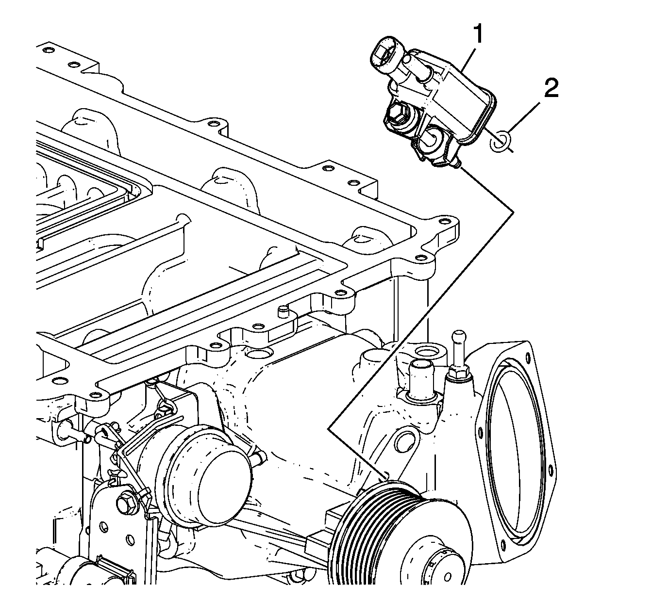
- Install a NEW evaporative emission (EVAP) valve seal (2).
- Install the EVAP valve (1) and tighten to 10 N·m (89 lb in).
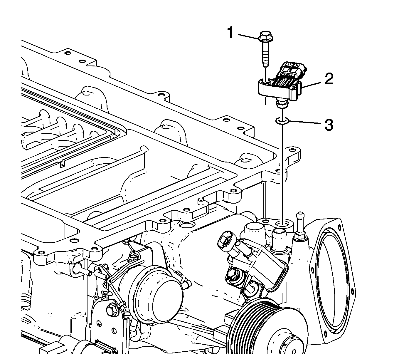
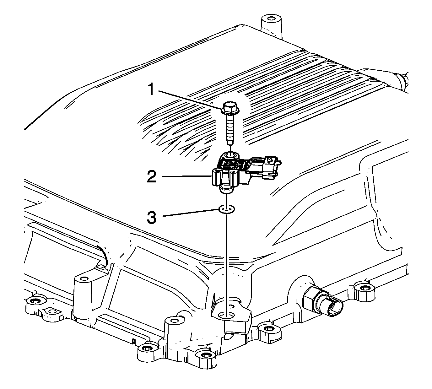
- Install a NEW inlet air pressure sensor seal (3).
- Install the inlet air pressure sensor (2).
- Install the inlet air pressure sensor bolt (1) and tighten to 10 N·m (89 lb in).
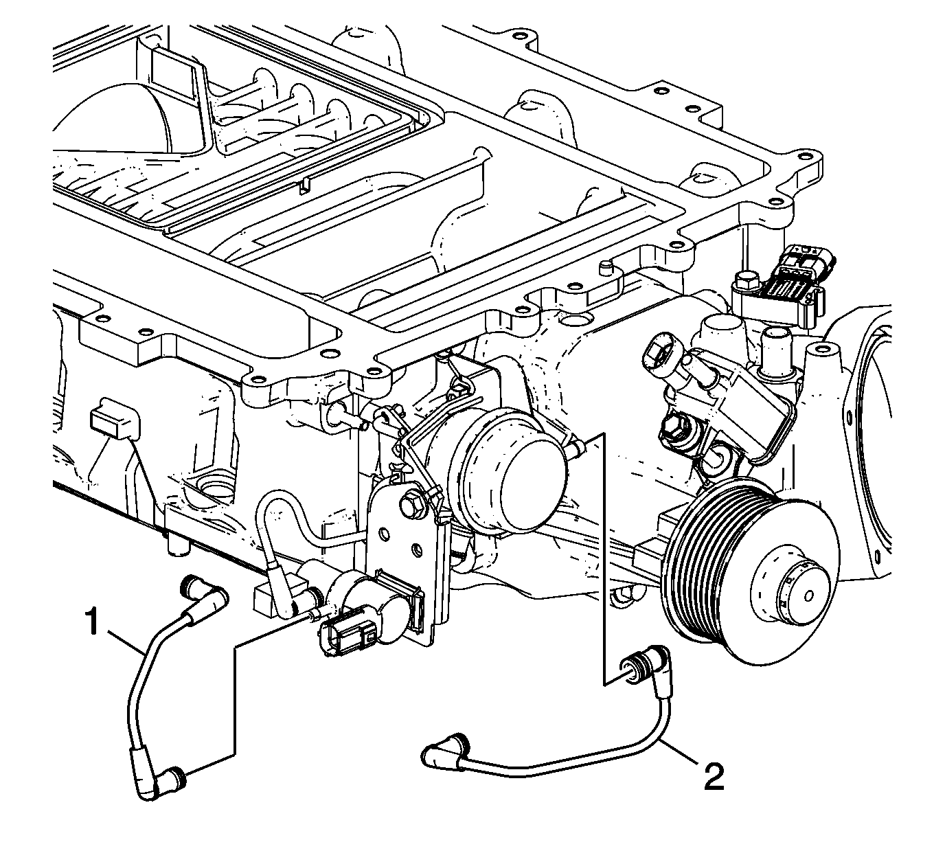
- Install the bypass valve vacuum tube (2).
- Install the bypass valve tube (1).
- Install the NEW insulator seals (1).
- Install the isolator pad (2) and bolts (1) and tighten to 10 N·m (89 lb in).
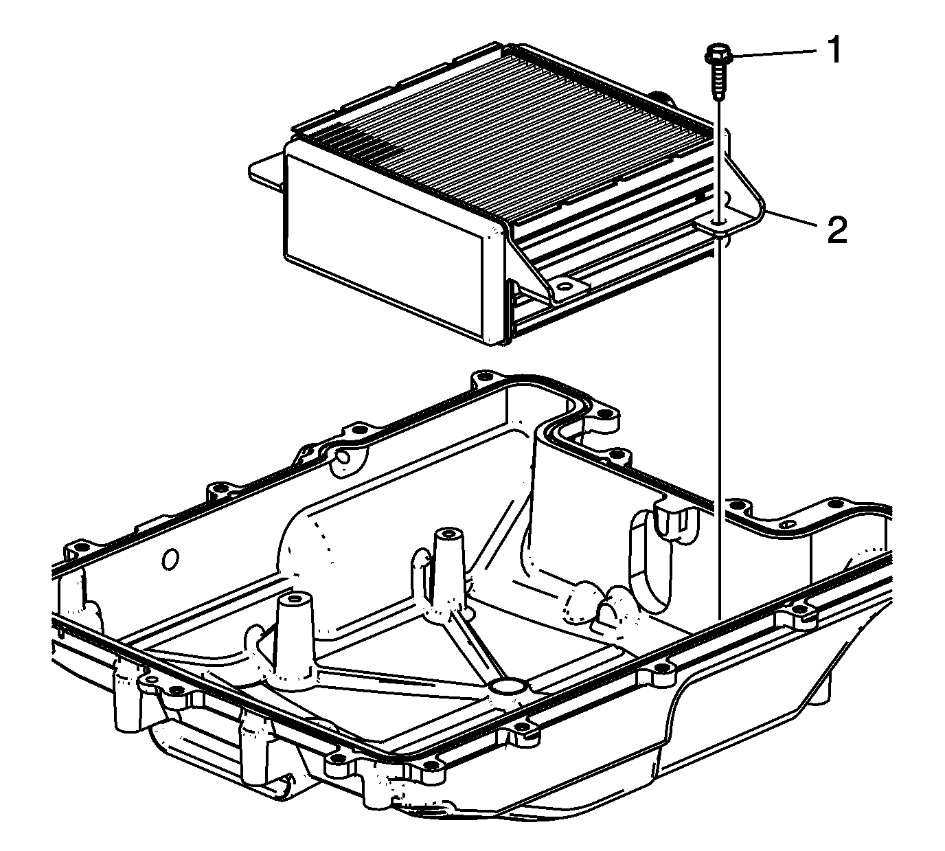
- Apply a 5 mm (0.2 in) band of threadlocker GM P/N 12345382 (Canadian P/N 10953489) or equivalent to the threads of the bolts.
- Install the charger air cooler (2) and bolts (1) and tighten to 10 N·m (89 lb in).
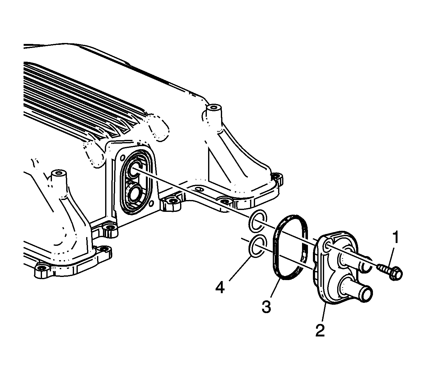
- Lubricate the seals with clean engine oil.
- Install the O-ring seals (4), seal (3), plate (2) and bolts (1) and tighten to 10 N·m (89 lb in).
- Install a NEW barometric pressure (BARO) sensor seal (3).
- Install the BARO sensor (2).
- Install the BARO sensor bolt (1) and tighten to 10 N·m (89 lb in).
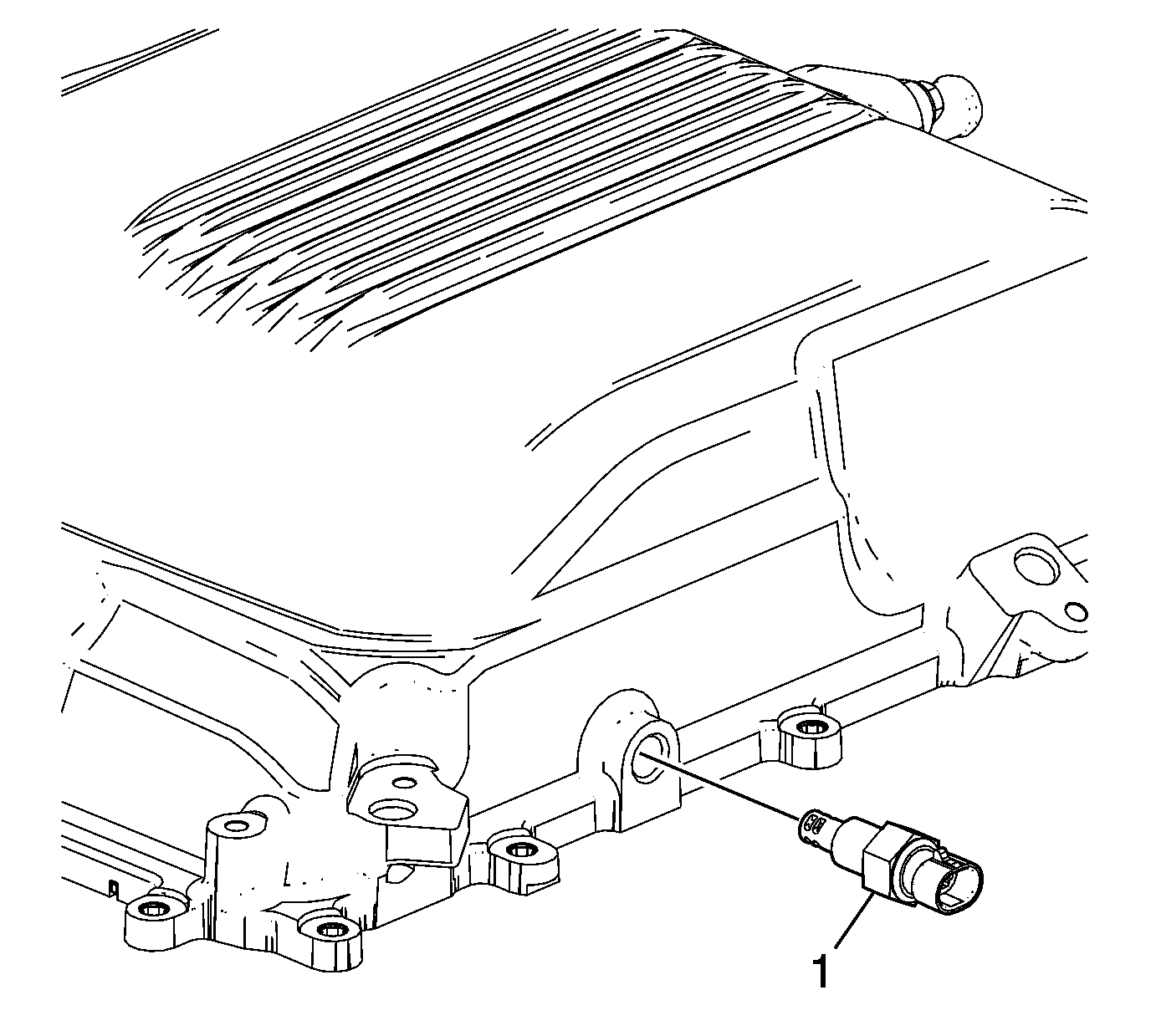
- Install sealant GM P/N 12346004 (Canadian P/N 10953480), or equivalent, to the threads of the sensor (1).
- Install the IAT sensor (1) and tighten to 20 N·m (15 lb ft).
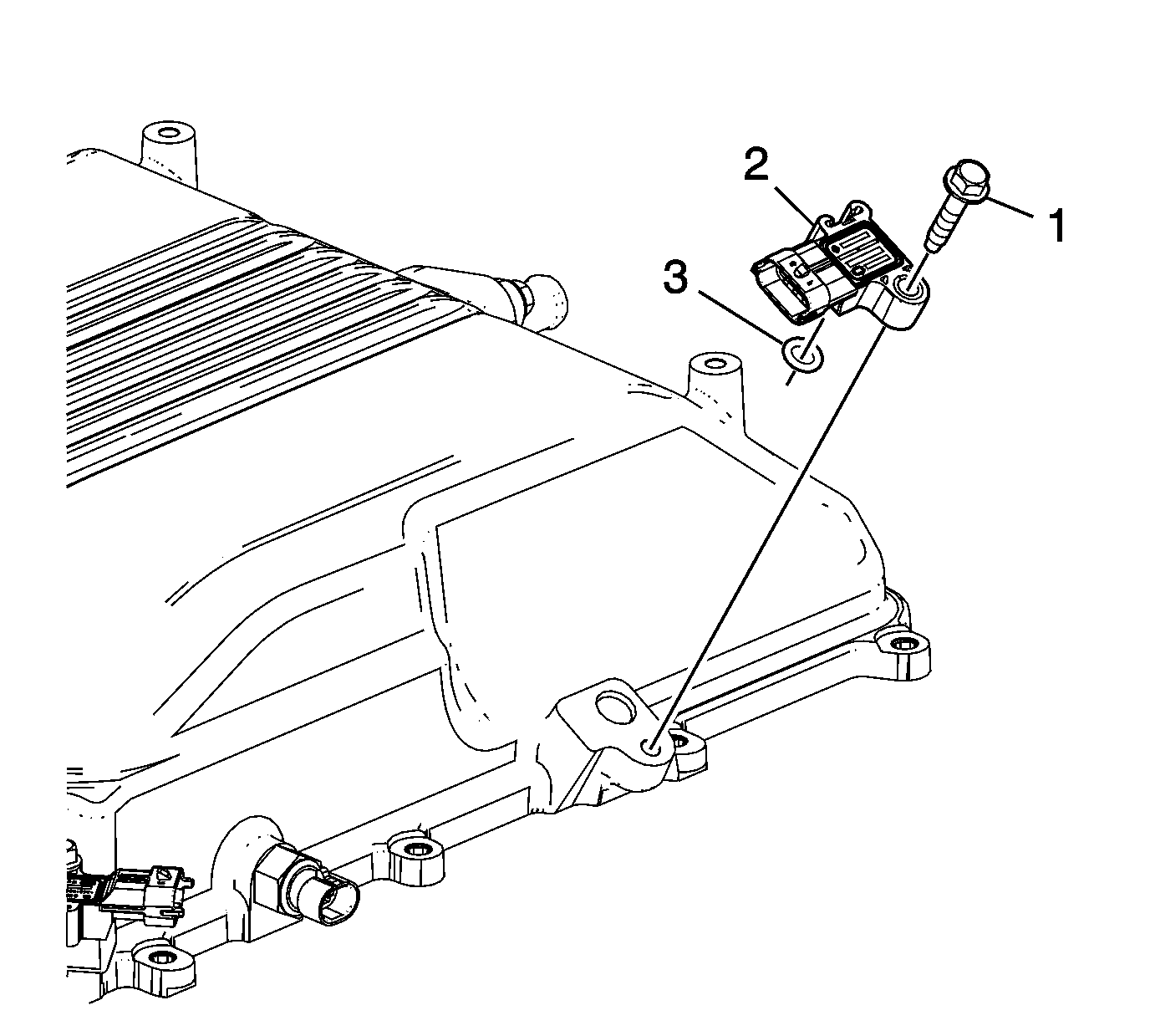
- Install a NEW manifold absolute pressure (MAP) sensor seal (3).
- Install the MAP sensor (2).
- Install the MAP sensor bolt (1) and tighten to 10 N·m (89 lb in).
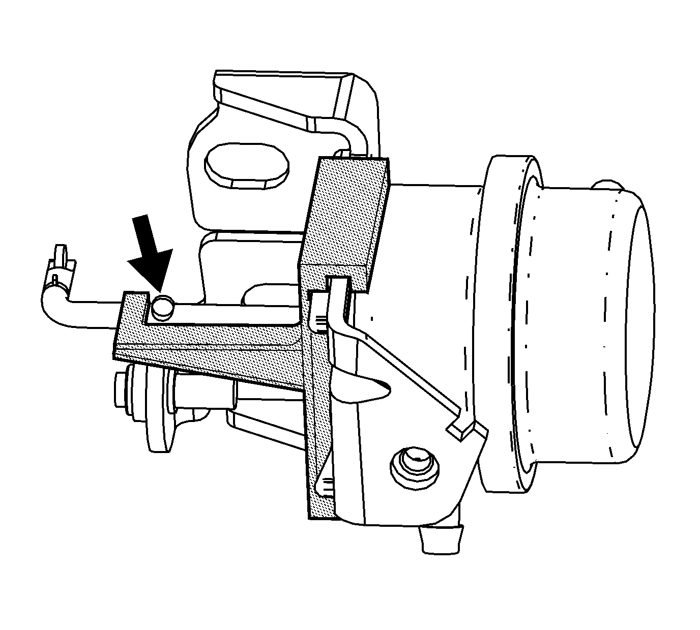
Note: The actuator adjustment tool is provided within the actuator parts kit.
Caution: Refer to Fastener Caution in the Preface section.
Supercharger Intercooler Pressure Testing
Special Tools
| • | EN-48974 Adapter Kit |
| • | J 46091 Charge Air Cooler Tester |
| For equivalent regional tools, refer to Special Tools |
- Rotate the regulator knob (3) counterclockwise until stop to reduce pressure to 0 kPa (0 psi).
- Connect the J 46091-1 to a shop air source (1).
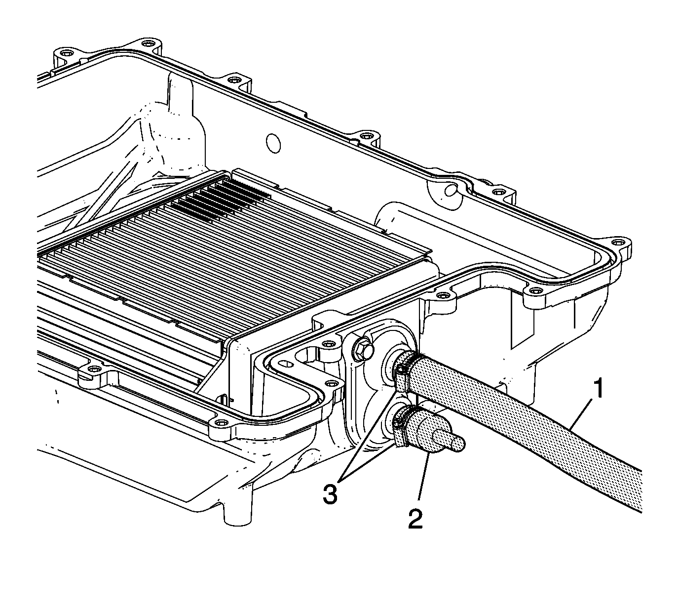
- Install the EN-48974 kit adapter hose (1), cap (2) and clamps (3) to the coolant inlet and outlet connections of the intercooler water manifold. Tighten the clamps until snug.
- Install the J 46091-1 to the EN-48974 kit adapter hose.
- Rotate the knob of the regulator slowly clockwise to increase pressure.
- With the intercooler pressurized to 69 kPa (10 psi) maximum, close the air inlet valve of the J 46091-1.
- Inspect for a drop in air pressure on the gage.
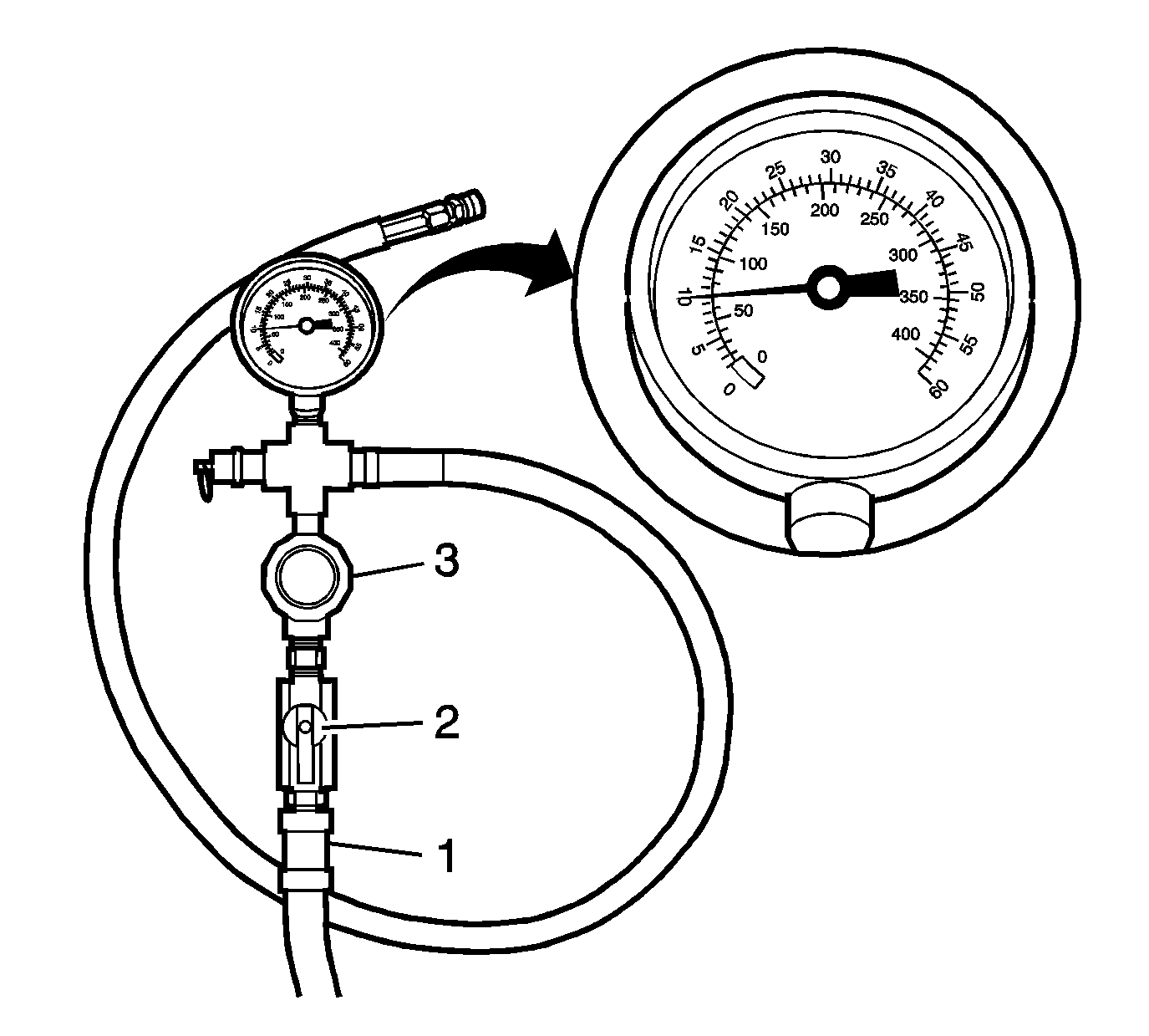
Warning: Do not apply greater than 69 kPa (10 psi) to the supercharger intercooler, this may damage the charge air cooler and other internal components within the intercooler.
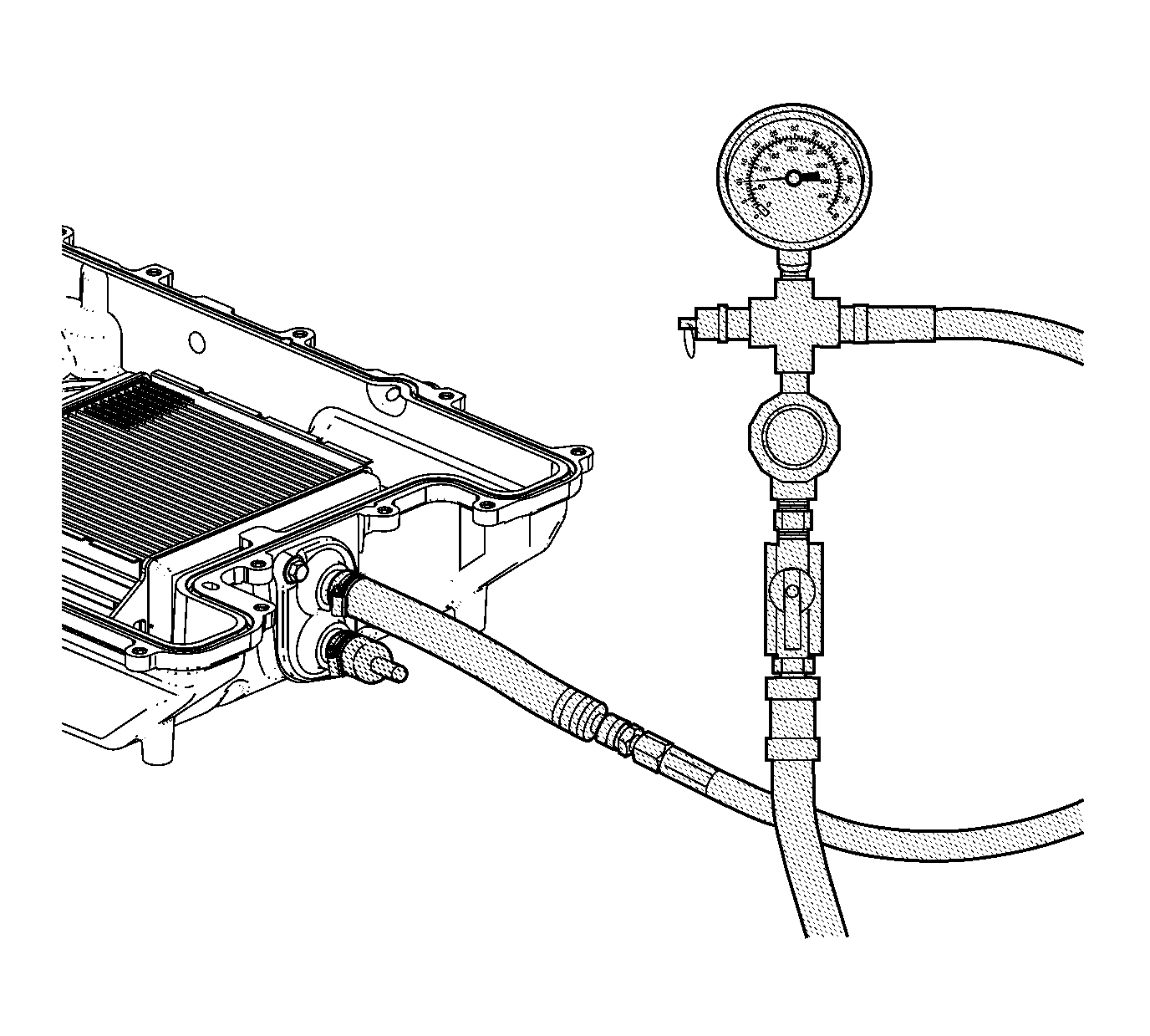
Note: The gage value should not exceed 69 kPa (10 psi). Adjust the pressure regulator as required.
| • | If a drop in pressure is noted, inspect for leaks at the tool connections, the charge air coolers, service bleed ports, assembly plant fill port, and water manifold-to-charge air cooler seal locations. |
| • | If no drop in pressure is noted, the intercooler can be installed onto the engine assembly. |
