Brake Pressure Modulator Valve Replacement CTS
Removal Procedure
Warning: Refer to Brake Fluid Irritant Warning in the Preface section.
Caution: Refer to Brake Fluid Effects on Paint and Electrical Components Caution in the Preface section.
Caution: To prevent equipment damage, never connect or disconnect the wiring harness connection from the EBCM with the ignition switch in the ON position.
- Place the ignition switch in the OFF position.
- Remove the RH front compartment sight shield. Refer to Front Compartment Sight Shields Replacement.
- Thoroughly clean the area around the EBCM of all dirt and debris.
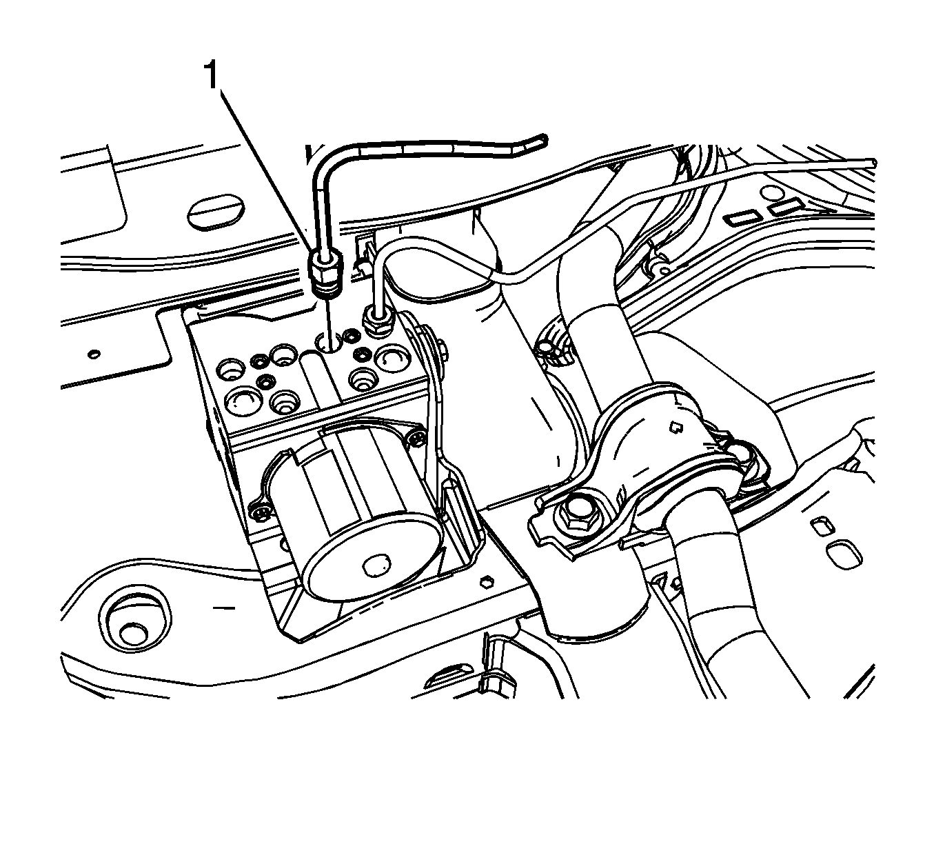
- Disconnect the secondary brake pressure modulator valve (BPMV) inlet brake pipe fitting (1).
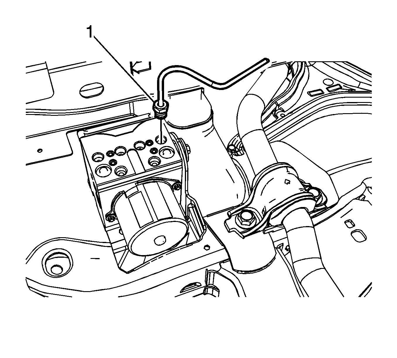
- Disconnect the primary BPMV inlet brake pipe fitting (1).
- Remove the electronic brake control module (EBCM). Refer to Electronic Brake and Traction Control Module with Brake Pressure Modulator Valve Replacement.
- Disconnect the LF brake pipe fitting (1).
- Disconnect the RR brake pipe fitting (1).
- Disconnect the LR brake pipe fitting (1).
- Disconnect the RF brake pipe fitting (1).
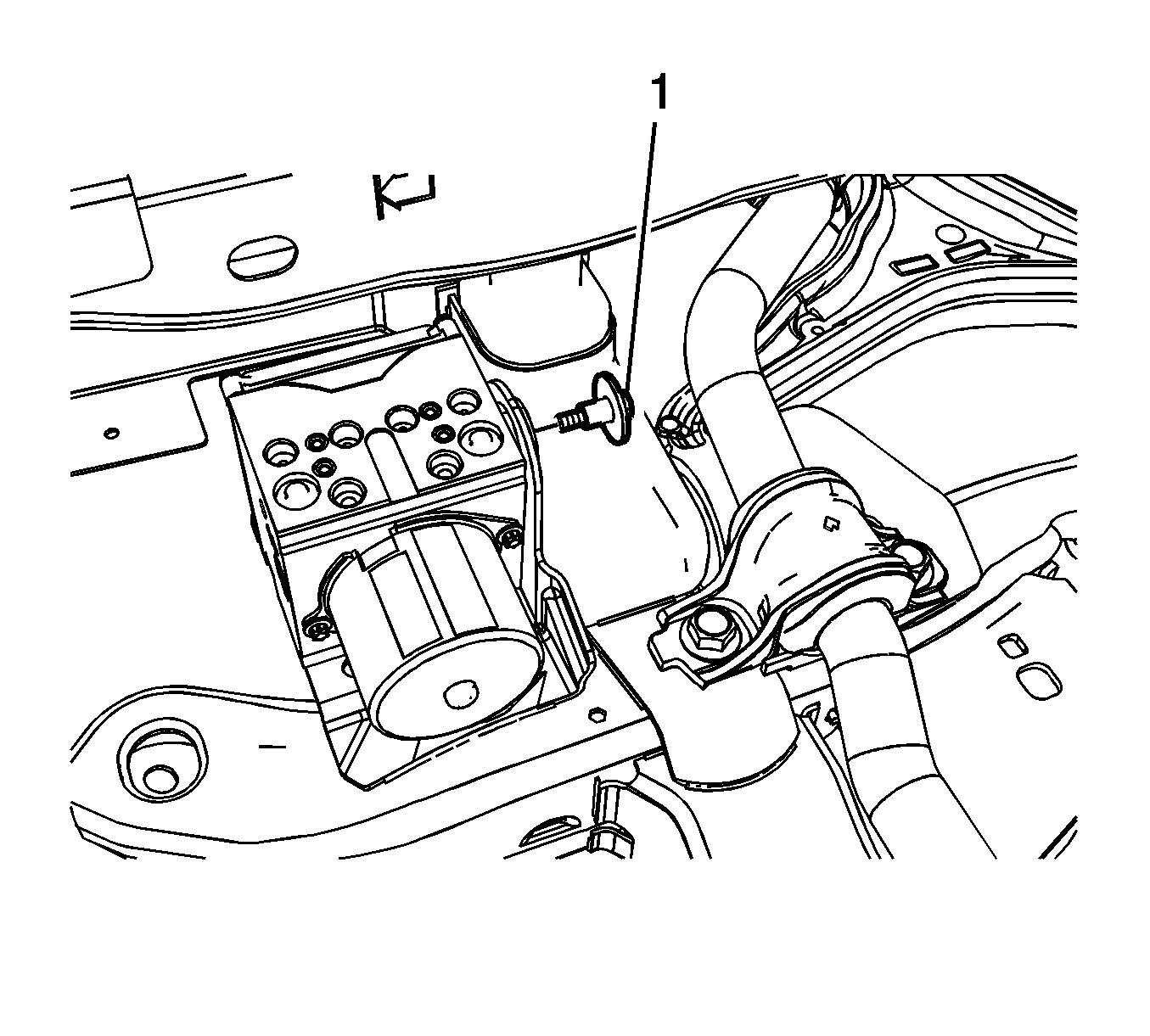
- Remove the BPMV bolt (1).
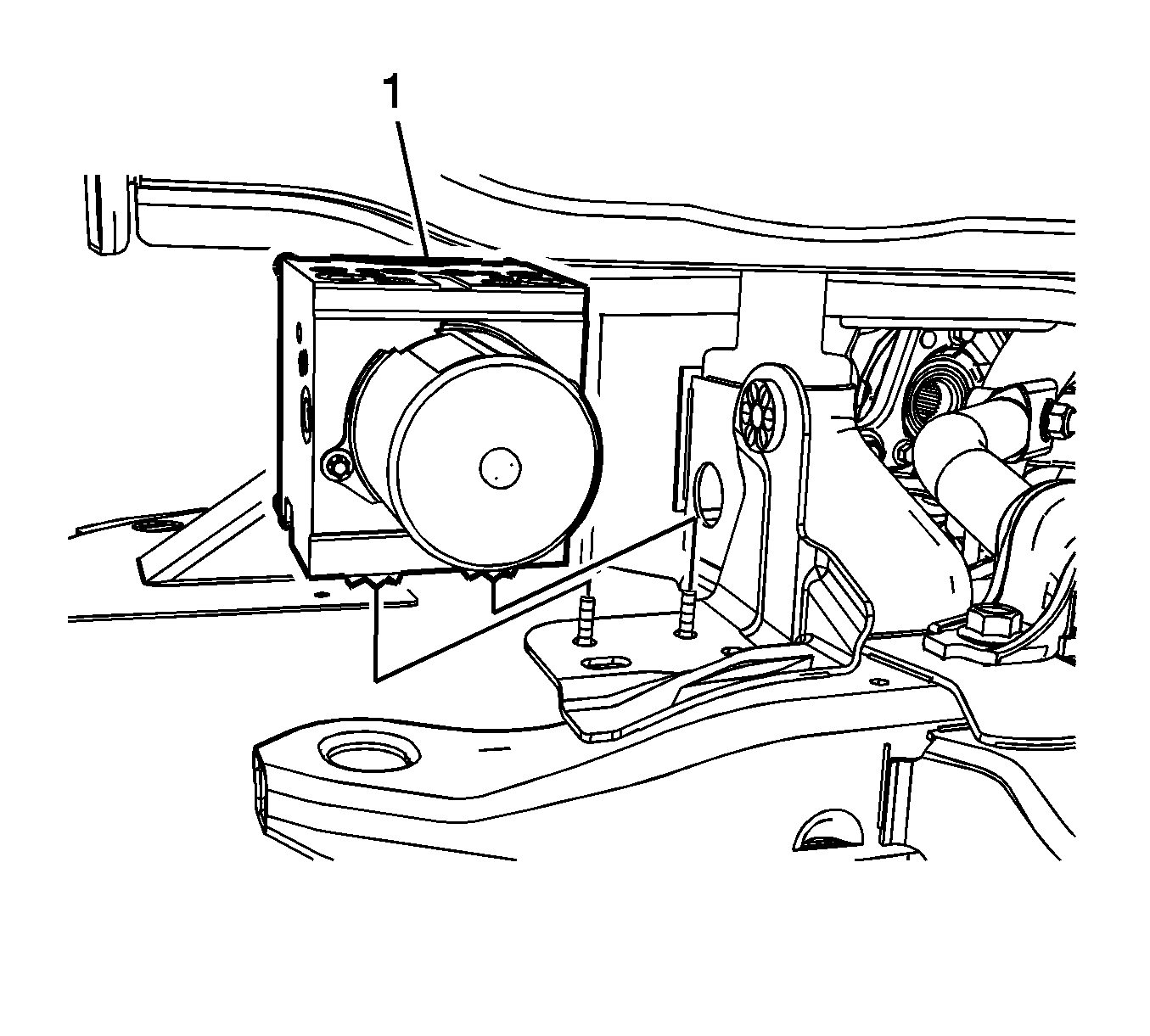
- Remove the BPMV (1).
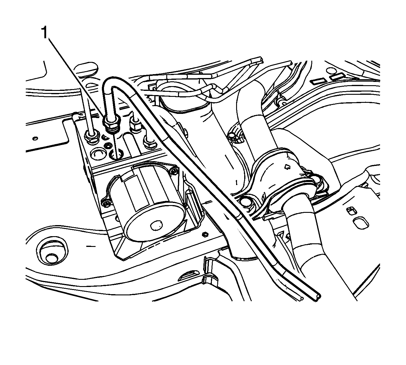
Cap the brake pipe fitting and plug the BPMV inlet port to prevent brake fluid loss and contamination.
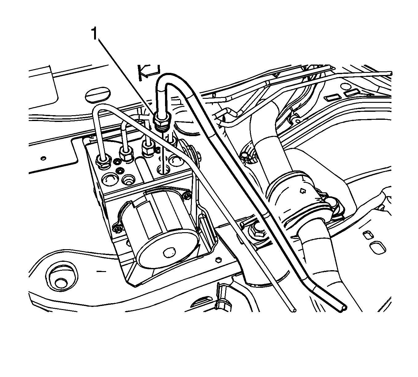
Cap the brake pipe fitting and plug the BPMV inlet port to prevent brake fluid loss and contamination.
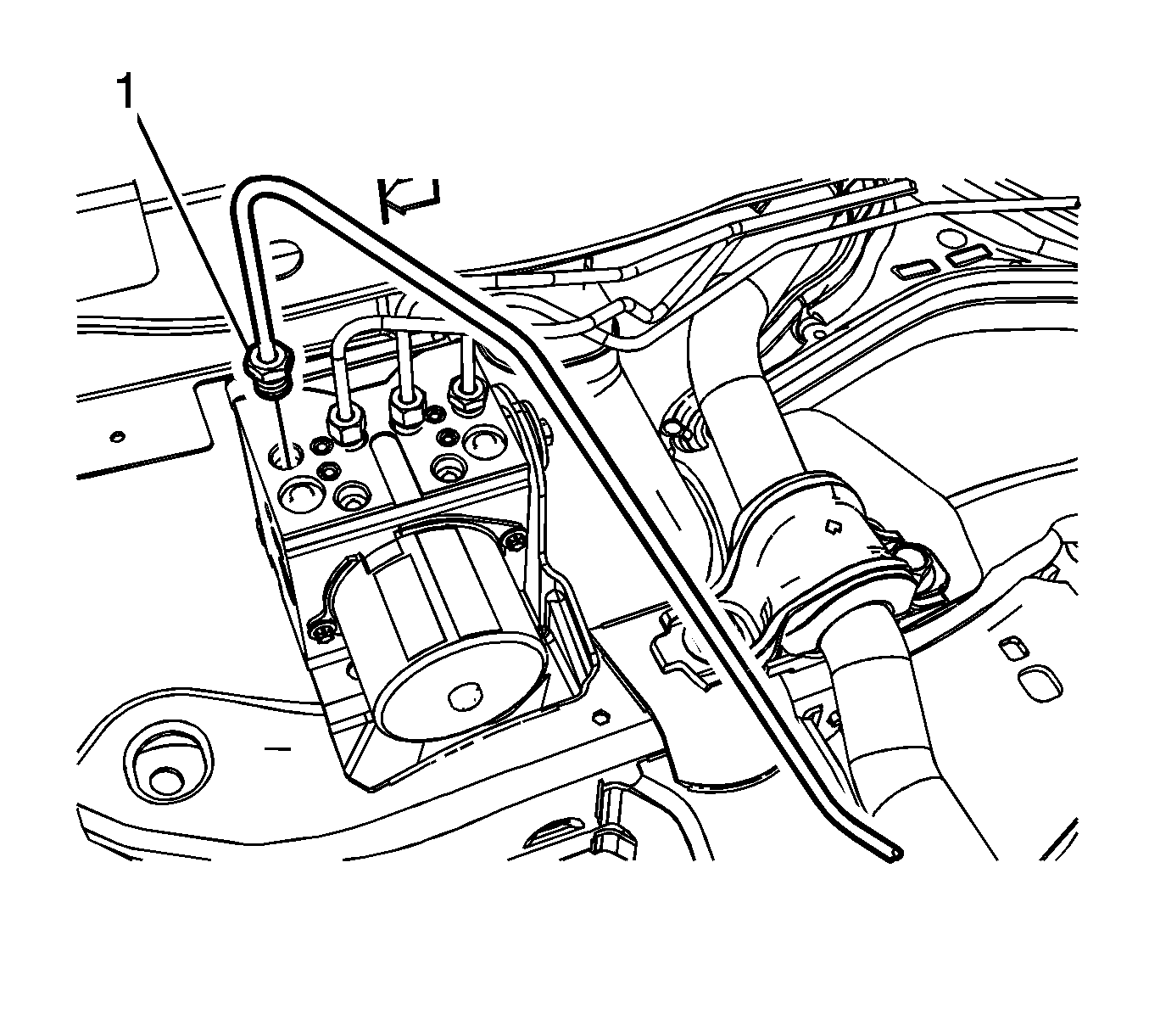
Cap the brake pipe fitting and plug the BPMV outlet port to prevent brake fluid loss and contamination.
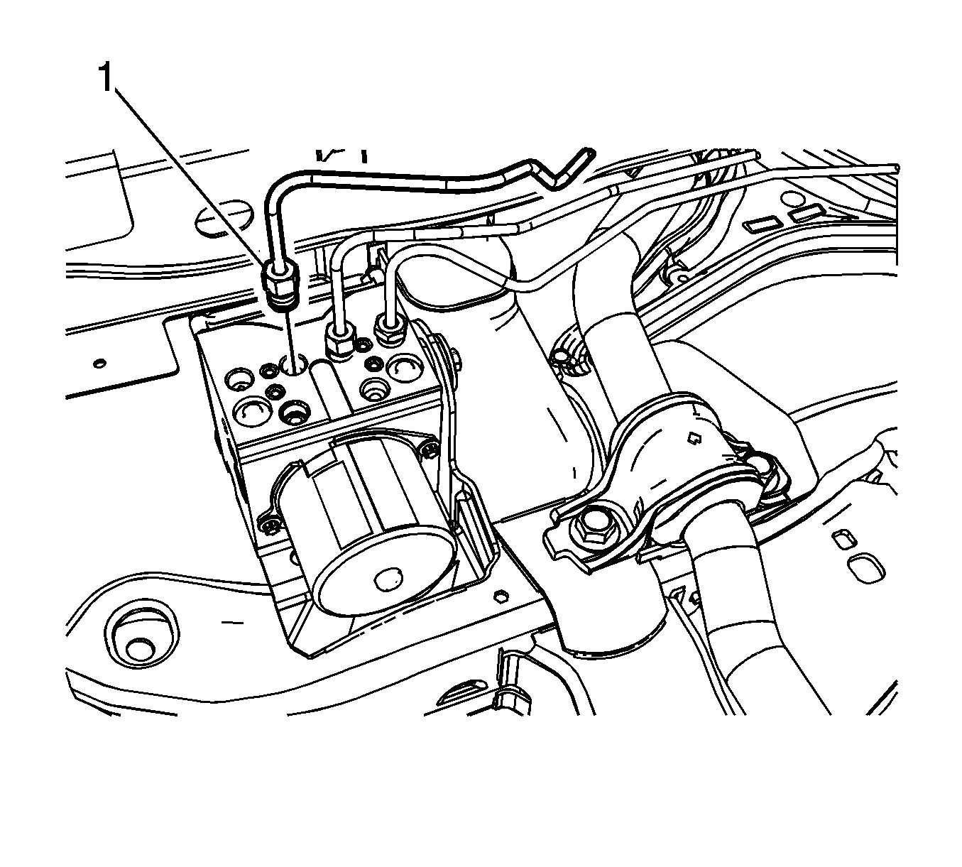
Cap the brake pipe fitting and plug the BPMV outlet port to prevent brake fluid loss and contamination.
Cap the brake pipe fitting and plug the BPMV outlet port to prevent brake fluid loss and contamination.
Cap the brake pipe fitting and plug the BPMV outlet port to prevent brake fluid loss and contamination.
Installation Procedure
- Install the BPMV (1).
- Install the BPMV bolt (1) and tighten to 12 N·m (106 lb in).
- Connect the RF brake pipe fitting (1) and tighten to 20 N·m (15 lb ft).
- Connect the LR brake pipe fitting (1) and tighten to 20 N·m (15 lb ft).
- Connect the RR brake pipe fitting (1) and tighten to 20 N·m (15 lb ft).
- Connect the LF brake pipe fitting (1) and tighten to 20 N·m (15 lb ft).
- Install the electronic brake control module (EBCM). Refer to Electronic Brake and Traction Control Module with Brake Pressure Modulator Valve Replacement.
- Connect the primary BPMV inlet brake pipe fitting (1) and tighten to 32 N·m (24 lb ft).
- Connect the secondary BPMV inlet brake pipe fitting (1) and tighten to 32 N·m (24 lb ft).
- Install the RH front compartment sight shield. Refer to Front Compartment Sight Shields Replacement.
- Bleed the hydraulic brake system. Refer to Hydraulic Brake System Bleeding.
- Perform the Antilock Brake System Automated Bleed Procedure.
- Perform the Diagnostic System Check - Vehicle.

Caution: Refer to Fastener Caution in the Preface section.


Brake Pressure Modulator Valve Replacement CTS-V
Removal Procedure
Warning: Refer to Brake Fluid Irritant Warning in the Preface section.
Caution: Refer to Brake Fluid Effects on Paint and Electrical Components Caution in the Preface section.
Caution: To prevent equipment damage, never connect or disconnect the wiring harness connection from the EBCM with the ignition switch in the ON position.
- Place the ignition switch in the OFF position.
- Remove the front compartment sight shield. Refer to Front Compartment Sight Shields Replacement.
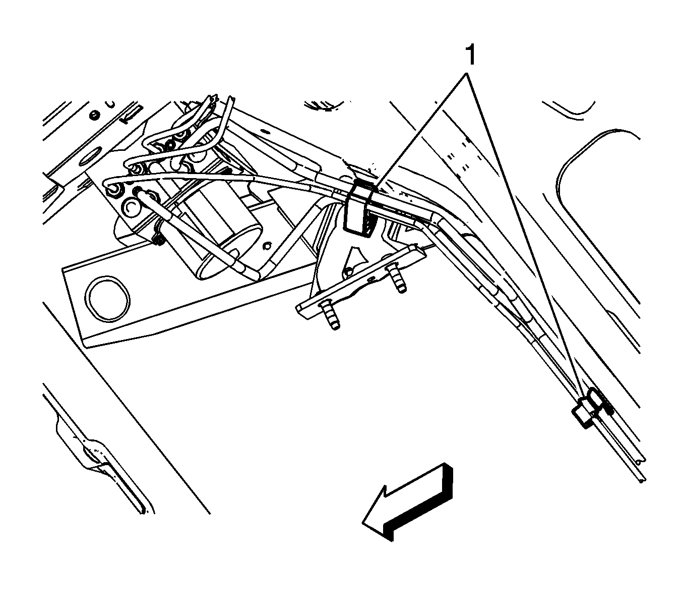
- Release the brake clips from the vehicle front frame (1).
- Thoroughly clean the area around the electronic brake control module (EBCM) and the brake pressure modulator valve (BPMV) of all dirt and debris.
- Disconnect the left front (1), master cylinder primary (2), and master cylinder secondary (3) brake pipe fittings from the BPMV.
- Release the brake pipe clips (1) from the right side engine compartment side rail.
- Disconnect the right rear (1), left rear (2), and the right front (3) brake pipe fittings from the BPMV.
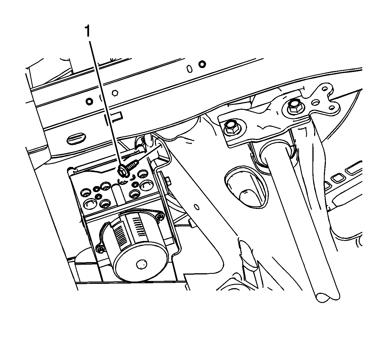
- Remove the BPMV assembly bracket bolt (1).
- Raise and support the vehicle. Refer to Lifting and Jacking the Vehicle.
- Remove the front air deflector. Refer to Front Air Deflector Replacement.
- Remove the right front wheelhouse liner. Refer to Front Wheelhouse Liner Replacement.
- Remove the washer solvent container fasteners and position the washer solvent container aside. Refer to Windshield Washer Solvent Container Replacement.
- Disconnect the electronic brake control module (EBCM) electrical connector
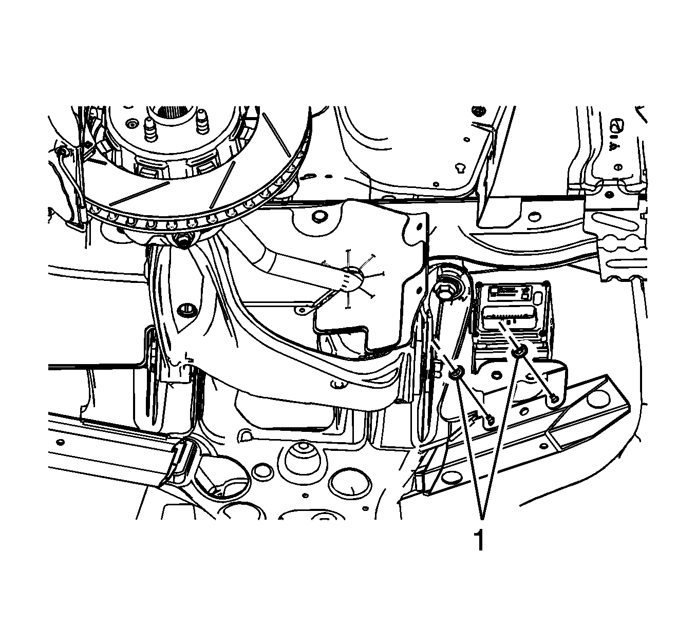
- Remove the BPMV bracket nuts (1).
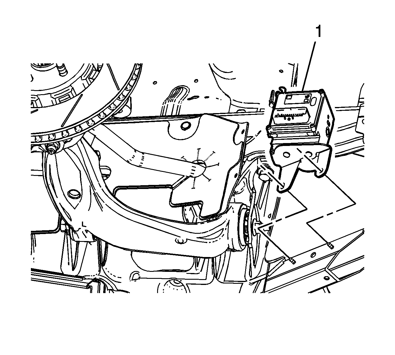
- Remove the BPMV and bracket assembly (1).
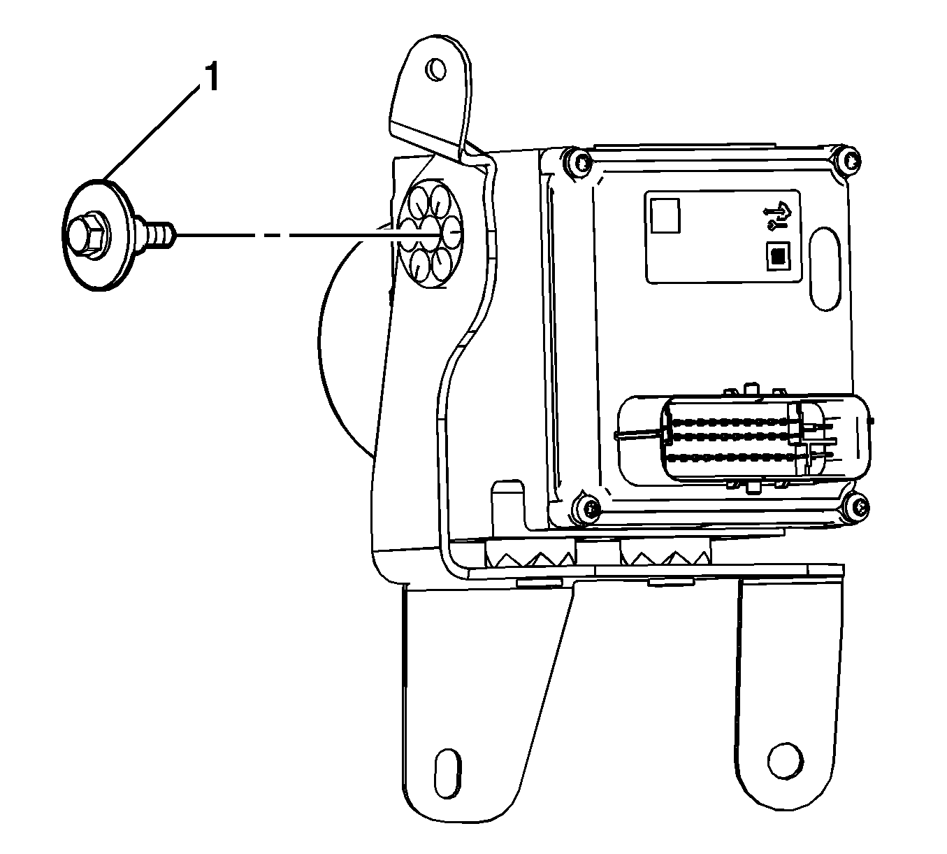
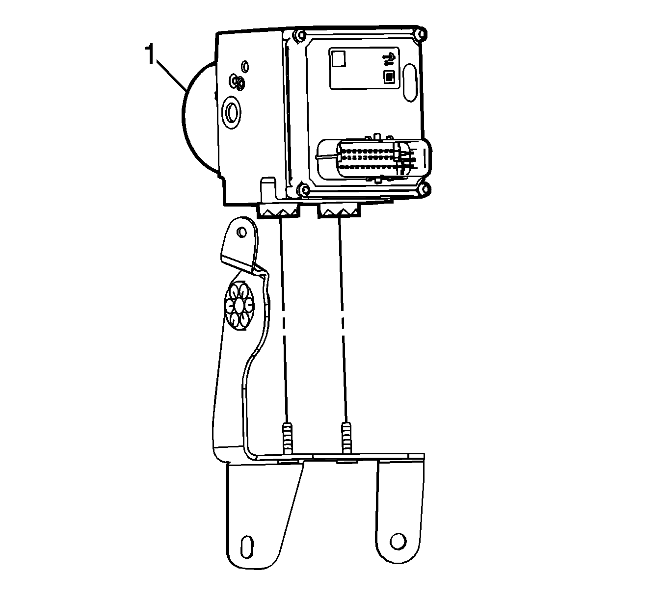
- Remove the BPMV bolt (1).
- Remove the BPMV (1) from the bracket.
- If installing a new BPMV, remove the EBCM. Refer to Electronic Brake and Traction Control Module with Brake Pressure Modulator Valve Replacement.
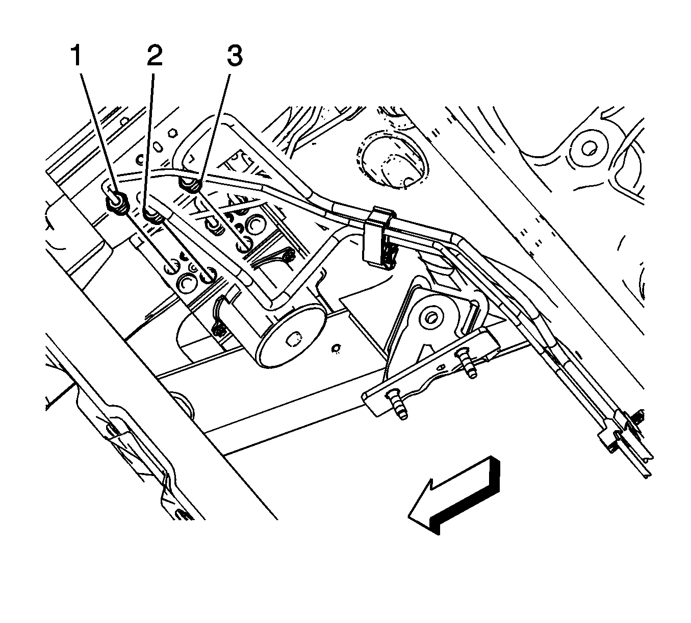
Note: Note the location of the brake pipes to the BPMV to ensure correct installation.
Cap the brake pipe fittings and plug the BPMV inlet and outlet ports to prevent brake fluid loss and contamination.
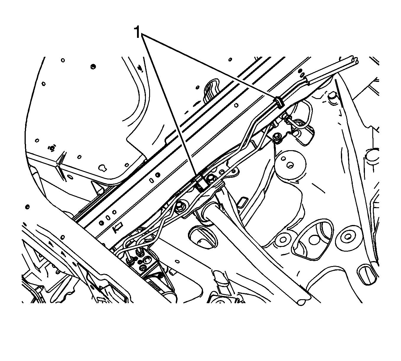
Note: Note the location of the brake pipes to the BPMV to ensure correct installation.
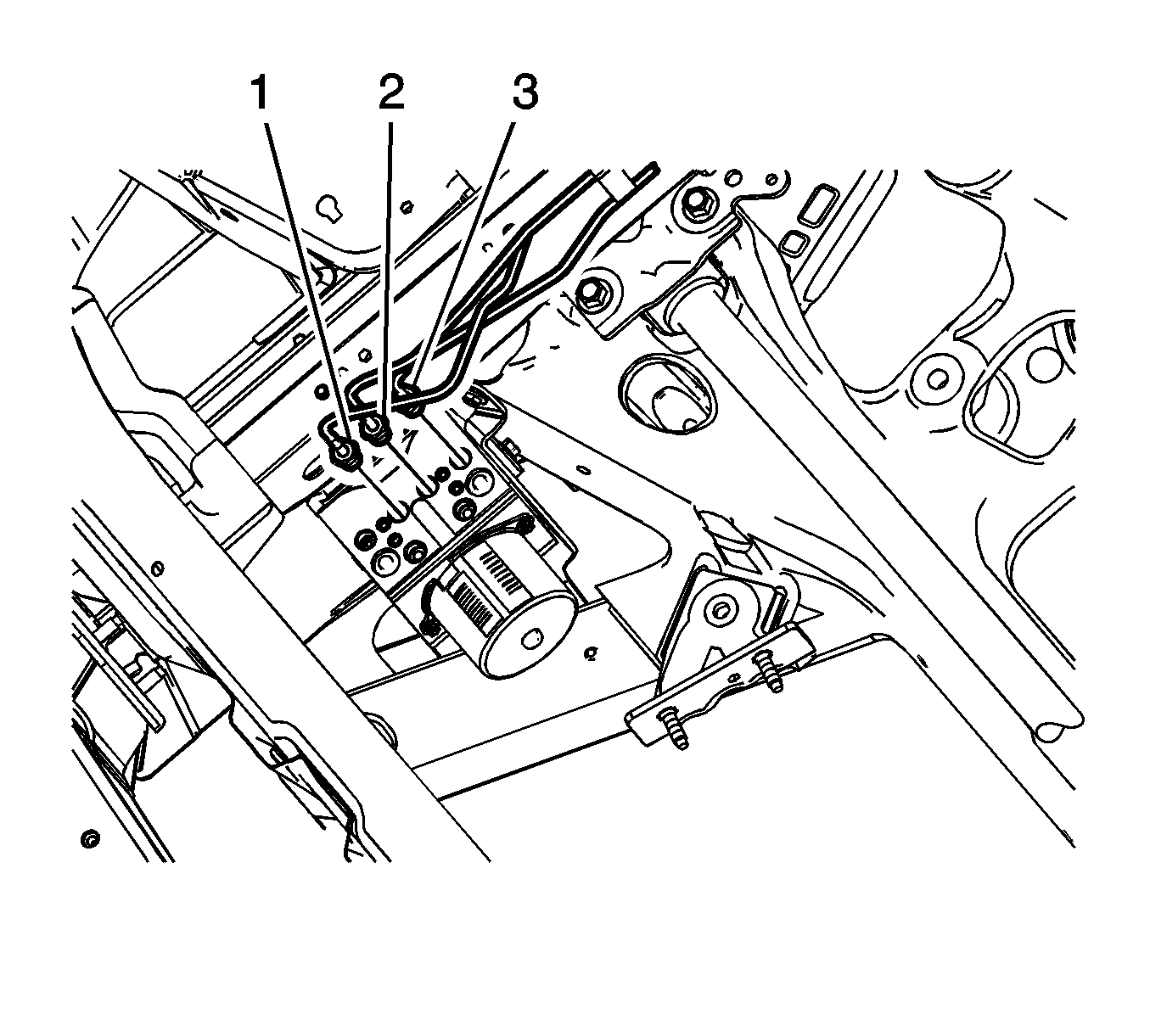
Cap the brake pipe fittings and plug the BPMV outlet ports to prevent brake fluid loss and contamination.
Installation Procedure
- If installing a new BPMV, install the EBCM. Refer to Electronic Brake and Traction Control Module with Brake Pressure Modulator Valve Replacement.
- Install the BPMV (1) to the bracket.
- Install the BPMV bolt (1) and tighten to 12 N·m (106 lb in).
- Install the BPMV and bracket assembly (1).
- Install the BPMV bracket nuts (1) and tighten to 12 N·m (106 lb in).
- Connect the electronic brake control module (EBCM) electrical connector
- Position the washer solver container and install the fasteners. Refer to Windshield Washer Solvent Container Replacement.
- Install the right front wheelhouse liner. Refer to Front Wheelhouse Liner Replacement.
- Install the front air deflector. Refer to Front Air Deflector Replacement.
- Lower the vehicle.
- Install the BPMV assembly bracket bolt (1) and tighten to 12 N·m (106 lb in).
- Connect the right rear (1), left rear (2), and the right front (3) brake pipe fittings from the BPMV and tighten to 20 N·m (15 lb ft).
- Install the brake pipes to the brake pipe clips (1) on the right side engine compartment side rail.
- Connect the left front (1) brake pipe fitting to the BPMV and tighten to 20 N·m (15 lb ft).
- Connect the master cylinder primary (2), and master cylinder secondary (3) brake pipe fittings to the BPMV and tighten to 32 N·m (24 lb ft).
- Install the brake pipes to the brake pipe clips on the vehicle front frame (1).
- Install the front compartment sight shield. Refer to Front Compartment Sight Shields Replacement.
- Bleed the hydraulic brake system. Refer to Hydraulic Brake System Bleeding.
- Perform the Antilock Brake System Automated Bleed Procedure.
- Perform the Diagnostic System Check - Vehicle.

Caution: Refer to Fastener Caution in the Preface section.


Note: Note the location of the brake pipes to the BPMV to ensure correct installation.

Note: Note the location of the brake pipes to the BPMV to ensure correct installation.


