For 1990-2009 cars only
Removal Procedure
- Raise and support the vehicle. Refer to Lifting and Jacking the Vehicle.
- Remove the tire and wheel. Refer to Tire and Wheel Removal and Installation.
- Lower the front of the rear cradle to gain access to the adjustment link bolt retaining nut. Refer to Rear Frame Replacement.
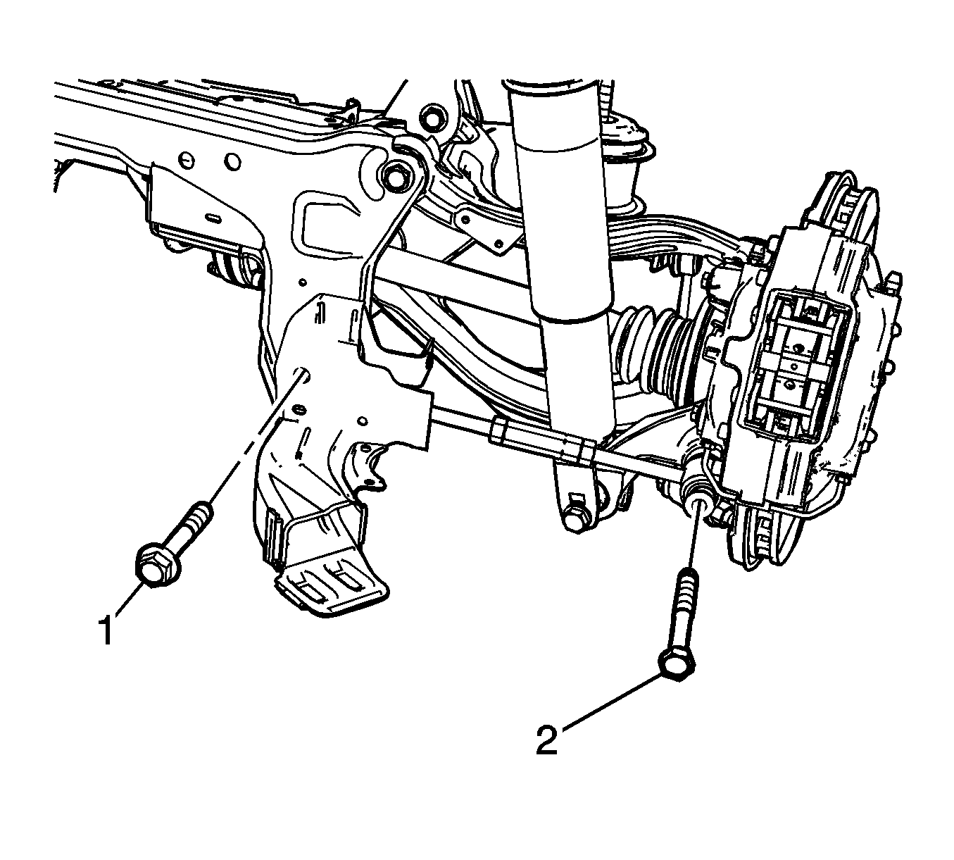
- Remove the adjustable link mounting bolts (1) and (2).
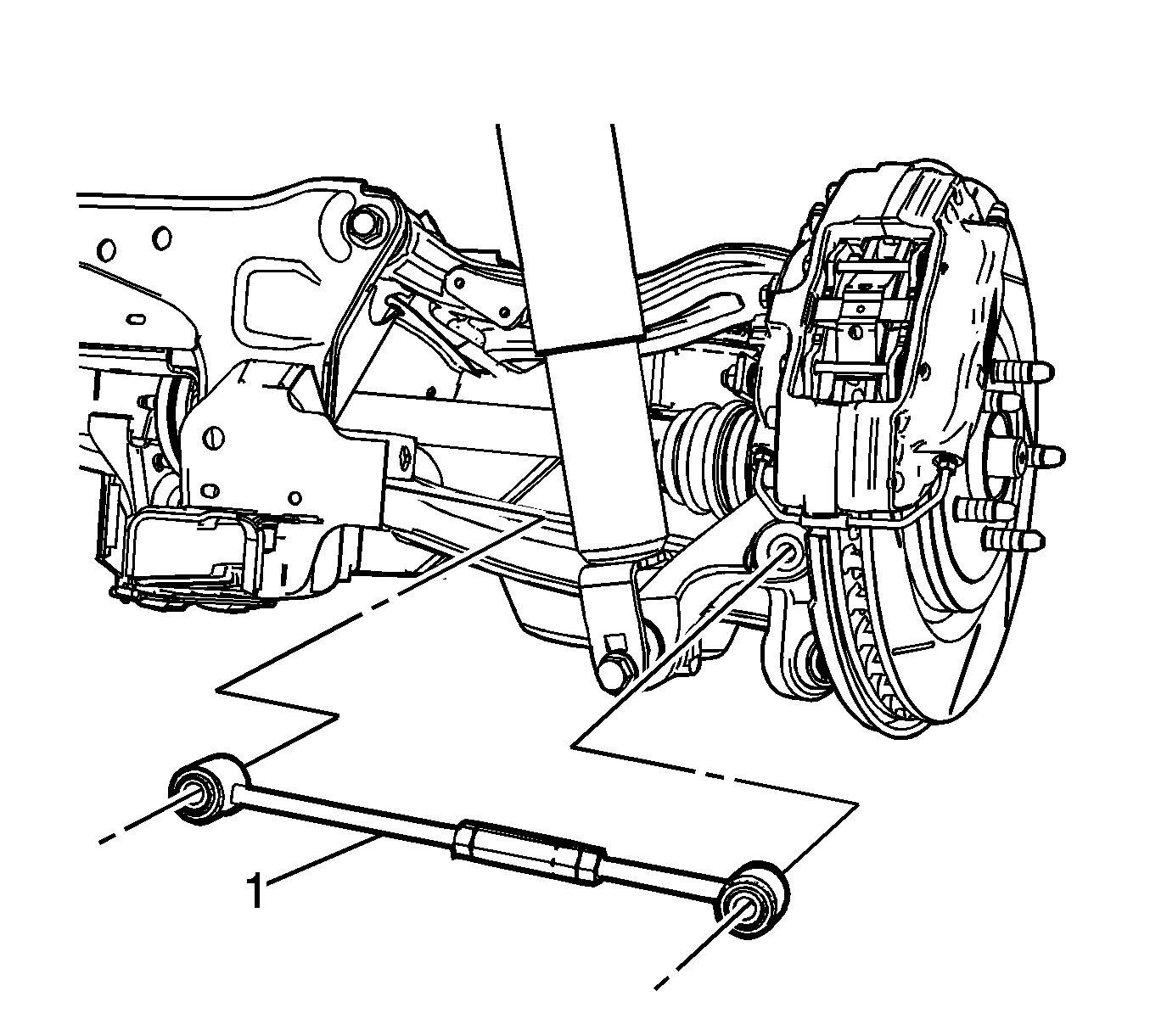
- Remove the adjustable link (1).


Installation Procedure
- Position the adjustable link (1) in the frame.
- Hand tighten the mounting bolts (1) and (2).
- Tighten the adjustable link mounting bolts (2).
- Tighten the adjustable link mounting bolts (1).
- Raise the front of the rear cradle. Refer to Rear Frame Replacement.
- Install the tire and wheel. Refer to Tire and Wheel Removal and Installation.
- Remove the support and lower the vehicle.
- Adjust the rear toe. Refer to Rear Toe Adjustment.


Caution: Refer to Fastener Caution in the Preface section.
Tighten
Tighten the mounting bolt to 160 N·m (118 lb ft).
Tighten
Tighten the mounting bolt to 170 N·m (125 lb ft).
