For 1990-2009 cars only
Special Tools
J 42162 Getrag Axle Side Gear Compressor
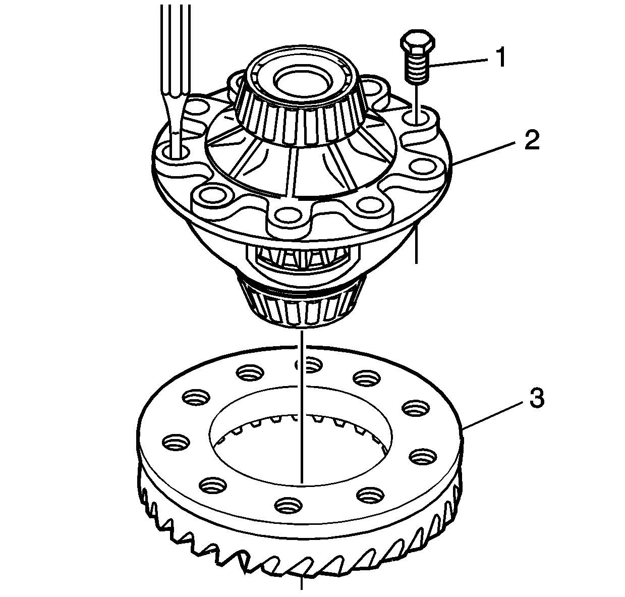
- Using a punch and a hammer, through a bolt hole, remove the ring gear bolts (1) and the ring gear (3) from the differential carrier (2).
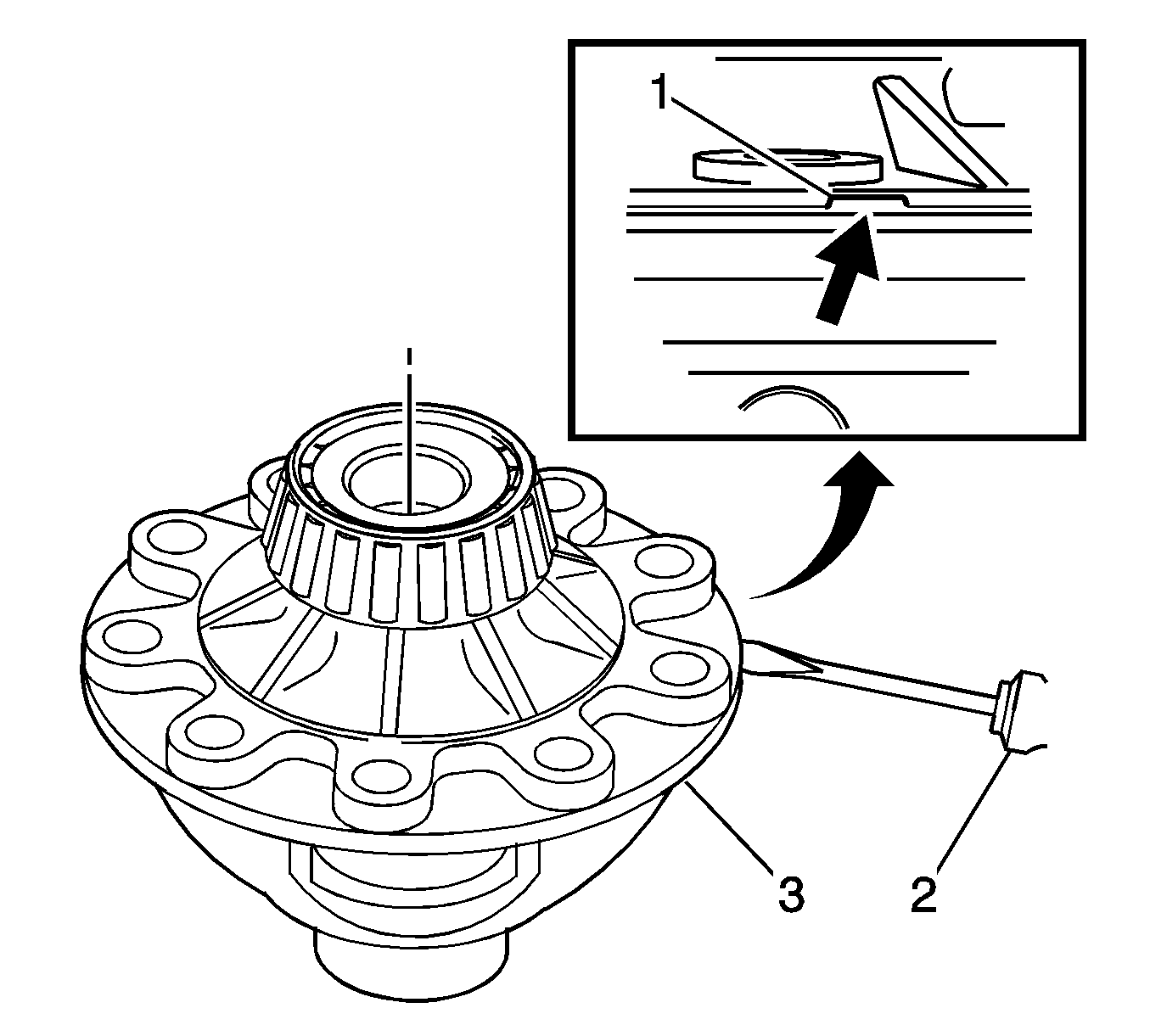
- Insert a screwdriver (2) in the differential carrier slot (1).
- Using the screwdriver (1), separate the differential carrier (3).
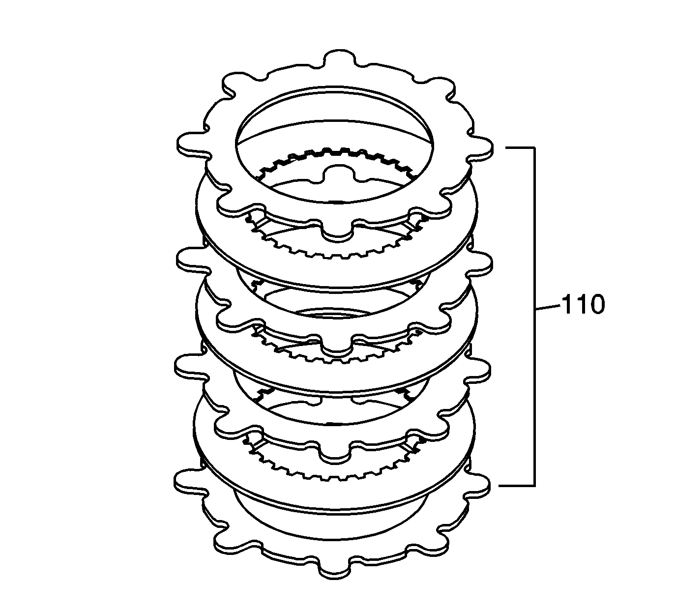
- Remove the axle side gear (107) and the clutch pack (110) from the differential carrier half (105).
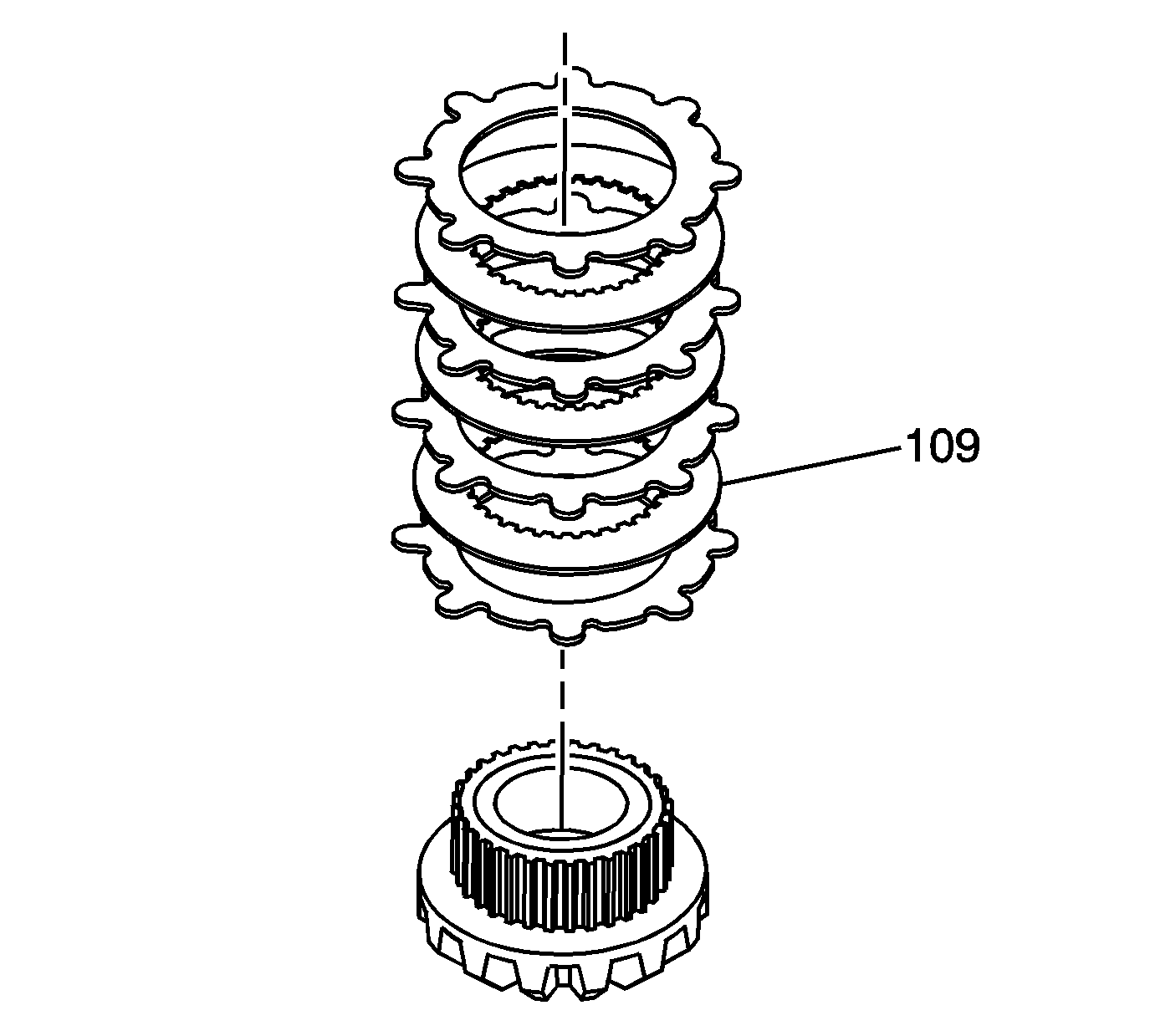
- Remove the clutch pack and axle gear from the right half. Note the thick pressure plate (109) side that has friction material faces away from the gear teeth.
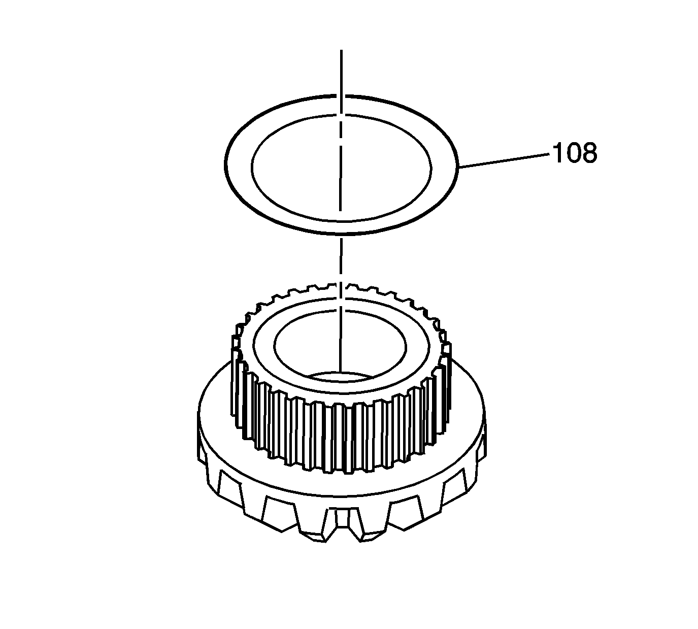
- Remove the beveled washer from the axle side gear. Note that the orientation of the beveled washer (108) faces out.
- Mark the clutch pack (110) to indicate the position of the components.
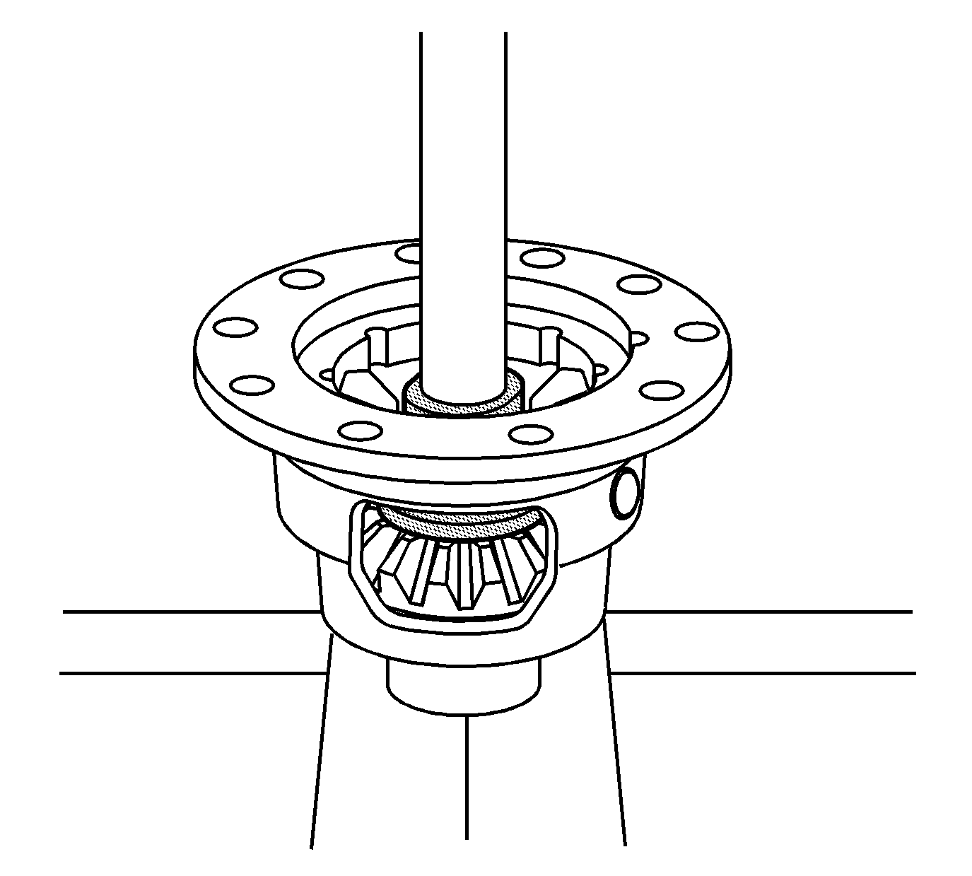
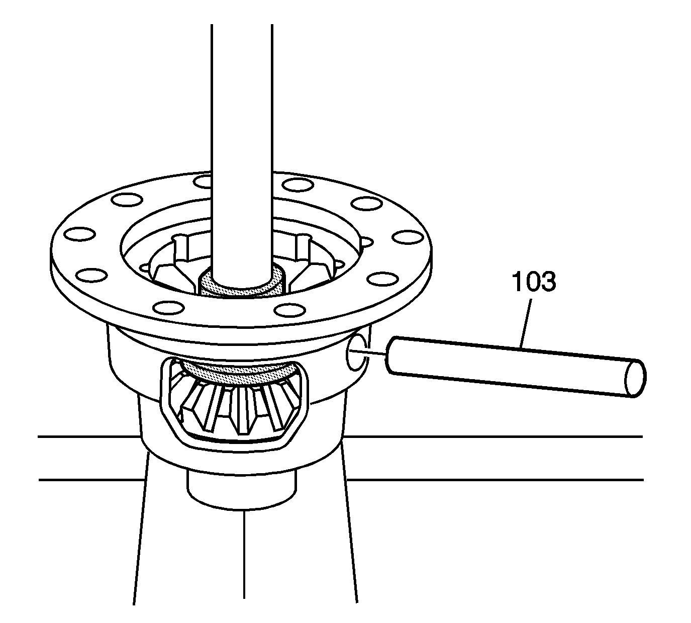
- Using the J 42162 and a press as shown, apply light pressure so the differential pinion gear shaft can be removed.
- Remove the differential pinion gear shaft (103). Release pressure from the press.
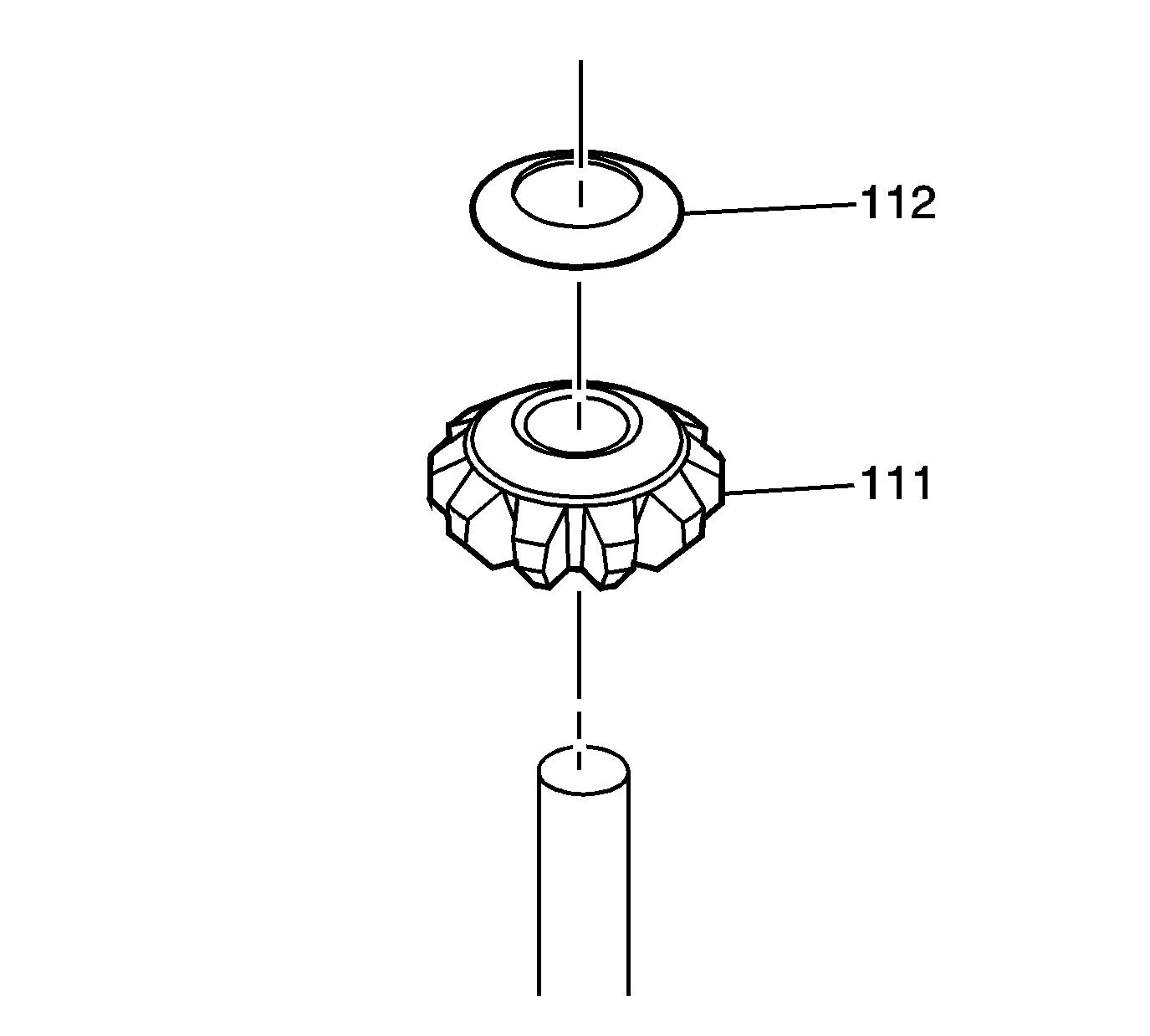
- Remove the pinion gears (111) and washers (112).
- Remove the clutch pack and axle gear from the left half. Note the thick pressure plate (109) side that has friction material faces away from the gear teeth.
- Remove the beveled washer from the axle side gear. Note that the orientation of the beveled washer (108) faces out.
- Mark the clutch pack (110) to indicate the position of the components.
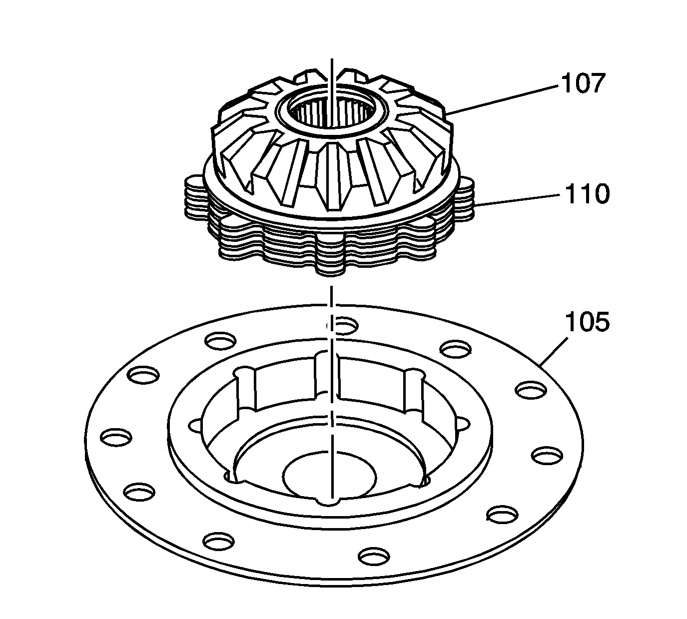
Important: Friction discs and separator plates develop specific wear patterns. During disc and plate removal, keep the components in the order in which they were removed.
